PARTsolutions® LLC, a leading provider of enterprise, digital parts management solutions for the standard part process, announced today the successful conclusion of their 7th annual Industry Forum on Digital Parts Management and Digital Product Catalogs. Over 200 companies from around the world attended, with keynote presentations by Adobe, Siemens, UNIVER, Festo, Rittal. The Forum program included exhibits by many solutions providers, workshops to evaluate new technology hands-on, and a meeting by the Automotive Working Group.
There were over 20 presentations by industry and corporate experts in three major areas of digital parts management:
• Intelligent process chain optimization, parts management and parts consolidation.
• Successful and measurable marketing with digital product catalogs.
• Technical documentation based on a digital product master.
The audience was also shown part consolidation and management in the packaging machine industry by Andritz Group, the PARTsolutions interface to SAP PLM by CIDEON, the power of marketing data that comes with digital catalogs by UNIVER, quality certification of standard parts at Siemens, and a whole range of related topics.
The newest PARTsolutions release 8.1 was also announced at the event. PARTsolutions Interactive digital catalogs are the choice of suppliers and engineers worldwide, because PARTsolutions is CAD, ERP, and PLM technology independent and can provide native data to all the major CAD systems, including Pro/E Wildfire®, CATIA®, UG-NX®, I-DEAS®, Autodesk Inventor®, SolidEdge®, SolidWorks®, and more.
Tuesday, February 28, 2006
PARTsolutions
FIRST Robotics High School Team
Dassault Systèmes announced that DELMIA is sponsoring the International Academy’s (Bloomfield Hills, Mich.) FIRST (For Inspiration and Recognition of Science and Technology) Robotics Team. The school is employing the DELMIA V5 Robotics suite as part of its software solution in the competition. DELMIA has offered a free limited license of its software to the other 100 Michigan schools participating in the FIRST Robotics event with 10 high schools to date taking advantage of this offer.
The FIRST Robotics program charges teams of high school students -- sponsored and assisted by mentor designers, engineers and programmers -- to design, assemble and test a robot capable of performing a specified task in competition with other teams. Remote-controlled robots piloted by students go head-to-head in short ball games, battling it out to earn points during a two minute round.
In 2006, the competition will reach over 28,000 high-school aged young people on over 1,125 teams in 33 regional events with teams participating from Brazil, Canada, Ecuador, Israel, Mexico, the U.K. and almost every state in the U.S.
Through its DELMIA Academic Partner Program, DELMIA software is being used as part of the curriculum at 20 universities, colleges, high schools, technical schools and other academic institutions throughout the United States and Canada. The DAPP program has shown that students are more likely to get hired into the workforce when they are already trained in the latest computer-aided digital design and manufacturing software programs, which are increasingly being implemented by today’s manufacturers.
DELMIA is a premier brand for digital manufacturing solutions, focused on two unique software applications that can be used to streamline manufacturing processes. DELMIA Automation provides solutions to digitally design, test and validate the control of a machine, workcell, or entire factory line and DELMIA PLM provides the process and resource capability to enable continuous creation and validation of manufacturing processes as related to the product throughout the entire product lifecycle.
A pioneer in the 3D software market since 1981, Dassault Systèmes develops and markets PLM application software and services that support industrial processes and provide a 3D vision of the entire life cycle of products from conception to maintenance.
Monday, February 27, 2006
Developing A Safer Way To Machine Magnesium
 Machining magnesium parts is risky business. The small chips and fine dust generated during cutting are highly flammable and pose a serious fire risk if not properly handled. These particles are commonly removed from the machine tool by means of a vacuum extraction system, in some cases using a hood mounted near the cutting tool to collect particles as soon as they are produced. Dry machining or use of minimum quantity lubrication (MQL) in conjunction with this extraction method allow chips to be recycled and can eliminate secondary part cleaning operations. However, auxiliary collection devices hamper both tool changes and machine high speed movements.
The use of oil-based coolants reduces, but doesn’t eliminate, the fire risk. In addition, the magnesium particles mixed in oil can’t be recycled, and the machined parts would require extensive cleaning to remove oil residue.
Spain’s IDEKO research institute, part of the Danobat Group, has recently concluded a multi-company R&D project that aimed to develop a safer method of high speed magnesium machining. The result is a novel system of extracting magnesium particles by vacuuming them through a hollow cutting tool and spindle, and into a collection container. Think in terms of through-spindle coolant delivery in reverse.
The key components in this system are cutting tool, tool holder and spindle. The tools have hollow shafts and carbide cutting tips with special geometries. A circular interpolating tool motion facilitates chip collection for the end mill tool version, as this yields smaller chips that are less likely to clog the flow through the system. Some tools also integrate a chip breaker to create even smaller, lighter chips. The system uses an HSK toolholder interface that is modified to prevent chip jams, and a through-coolant-type draw bar that is similarly tailored for optimal flow in reverse. (See online video above that shows an end mill pocket milling valve reliefs in the top of a piston.)
IDEKO determined that the system provides an average chip extraction rate of 95 percent for magnesium chips. Additional testing is being performed to verify system applicability for machining aluminum alloys. The key for use with non-magnesium materials is to generate chips that are small enough to be easily transported through the tool and the system’s other internal passages.
Friday, February 24, 2006
Non-Contacting Rotary Sensor
 Based on magnetic field technology, Novotechnik RFC sensors have no moving or mechanical parts attached to wear or break. A magnetic assembly affixed to the shaft is physically separated from a sensor with an embedded integrated circuit that provides analog output representing the calculated angle range - from 30° to 360° in 10° steps.
Since the two components are completely separate and there are no moving or mechanical parts to wear or break, the RFC Series sensors have virtually unlimited operating life.
The sensor is sealed to protection class IP 69 so it is not sensitive to dirt or dampness. Electrical connections are made via a shielded cable with 3 lead wires. A redundant output is available with six leads.
The RFC Series provides 12-bit resolution, independent linearity to 0.5% of measurement range and repeatability of <0.03%. The rotary sensor is available with two voltage output options.
Applications include industrial valves, automotive suspension systems, and more in the automotive and marine industries.
Polymer Adhesive low-viscosity formula
 Master Bond has successfully developed a new highly flexible two component epoxy resin compound called EP40 which features outstanding shear and peel strength especially designed for bonding, sealing and casting engineering plastics and metals. This compound has been formulated to cure readily at ambient or more quickly at elevated temperatures with a convenient non-critical one (1) to one (1) mix ratio, weight or volume.
The Master Bond Polymer System EP40 has been found to provide an excellent solution for applications requiring the inherently attractive strength properties of epoxy resins together with enhanced flexibility and peel strength characteristics. Additional desirable performance characteristics of this unique epoxy compound include superior resistance to thermal cycling and mechanical vibration and shock. Electrical insulation properties are excellent even after prolonged exposure to hostile environmental conditions.
The Master Bond Polymer System EP40's low viscosity facilitates bonding, sealing, casting and other processing operations. The availability of versatile cure schedules further simplifies the application of this unique polymer compound. The excellent adhesion of EP40 to a wide variety of substrates ranging from engineering plastics such as polycarbonates, acrylics and ABS to steel, aluminum and other metals is particularly noteworthy. Thus shear and peel strength for bonding polycarbonates are in the order of 1000psi and 20 pli respectively while steel and aluminum bonds yielded shear strength values as high as 1800 and 1500 psi.
Master Bond polymer System EP40 has an impressively wide service temperature range of -100°F to +230°F. The Master Bond EP40 compound is the preferred choice for many electronic potting and encapsulation applications, two component adhesives and sealants, coatings and composite uses wherever substrates with different thermal expansion properties must be combined to form electronic and/or mechanical assemblies.
Motor Type Vs. Machine Design
 Do linear motors make a machining center better? Or, more specifically, do they improve dynamic stiffness? A study conducted by machine tool builder Mori Seiki suggests that the answer is yes, but with an important caveat. Applying linear motors alone is not necessarily the most effective way to improve stability. When it comes to dynamic stiffness, changing the machine design may offer more potential for improvement.
Mori Seiki managing director Kazuyuki Hiramoto supplied the data for the graph on the following page. The numbers represent the test results for trials run on a test machine with and without linear motors, and with and without a machine-tool design concept called “Driven at the Center of Gravity,” or DCG. What the numbers specifically measure is the amount of vibration that resulted after the machine was moved and stopped. The point of the comparison is that some vibration can be attributed to how the axis motors work, but potentially more of the vibration results from where the force of those motors is directed.
Axis motors on machining centers tend not to apply their force through the center of gravity of the moving elements, but instead they tend to apply it to one side or the other. Dr. Hiramoto says this runs contrary to a principle we all intuitively know. That is, when moving a heavy weight, we try to push at the center. The problem with not driving through the center of gravity on a machining center is that machine tools are—in a sense—squishy. Even a push by hand might deform a machine by 10 microns. The slight twisting of machine elements that comes from linear axis forces pushing off-center can cause vibration that may ultimately affect the surface quality of the part and the life of the tool. Machining center users sometimes deal with this vibration by making gradual starts and stops.
The company’s DCG machines do try to push through the center of gravity. The machines use ballscrews, and the very challenge in realizing the DCG concept is that the lines through the center of a machining center may not leave room for a ballscrew. The spindle occupies a central location on a machine, and so might a rotary table. In these cases where some other basic component of the machine interferes at the center, the DCG machine uses two ballscrews instead, one ballscrew on either side, so that the resultant force still does drive through the center.
Related Posts
Thursday, February 23, 2006
Tools For Titanium
The design of the new Boeing 787 Dreamliner relies extensively on composite materials. That aspect of the plane has received attention—rightly so. However, composites aren’t the only reason why this plane is materially different. Compared to other commercial aircraft, the 787 also uses significantly more parts made from titanium. To machine just the titanium necessary to fill the orders for this one aircraft, Boeing will need to employ 1,000 spindles within the next 3 to 5 years.
That estimate comes from Keith Young, an engineer/scientist with Boeing’s Advanced Manufacturing R&D group in Saint Louis, Missouri. Part of Dr. Young’s job is to help those spindles work more effectively for Boeing. The challenge of titanium aircraft parts is to make them lighter by making walls and floors thin, and by reducing the parasitic weight of stock remaining in corners. Through experiments, Dr. Young and others in this group develop machining techniques for achieving these goals. They tell Boeing’s designers what machined features are possible in titanium parts, and they educate machining suppliers about how to produce those features.
Some of this knowledge has already been developed for titanium parts in military aircraft. However, commercial aircraft differ in scale. Part dimensions, most significantly pocket depths, are bigger. A deep pocket in a military aircraft part is 3 inches. On 787 components, pockets in titanium can be 6 inches deep. Whereas tool length-to-diameter ratios of 3:1 or 4:1 have been traditional for machining aircraft titanium, the newer parts call for ratios of 6:1 or 8:1, and the difference fundamentally affects the choice of tooling. For example, where an inserted milling tool might typically feature a steel shank, the deeper pocket could call for a stiffer carbide shank to minimize deflection and help prevent chatter.
Tom Talley is another Boeing engineer/scientist in Saint Louis. Together, he and Dr. Young shared some of what they’ve learned about the tooling choices suited to the newest generation of titanium parts. Their recommendations provide the basis for this article, but it’s worth qualifying just how far those recommendations go. Boeing may endorse machining techniques, the two men say, but it doesn’t endorse cutting tool suppliers. Some tool suppliers are mentioned below because they offer what Mr. Talley and Dr. Young consider to be clear examples of useful tooling styles. However, in most of these cases, other tool companies do offer comparable designs. A competing tool might be the more effective choice in a particular shop’s process. The tools cited here are simply illustrations, showing some tool features suited to the part features that are increasingly important to Boeing.
Tools For Roughing
The Weldon Crest-Kut tool shown in Figure 1 features irregular geometry along the flutes. The importance of this irregularity has to do with eliminating chatter.
Chatter is the limiting factor in many milling processes. Its severity at a certain depth of cut often prevents the tool from achieving the much heavier depth of cut that the tool and the spindle would otherwise allow. Chatter is partially caused by the regular waviness that a tool’s consistent geometry imprints upon the machined surface. With the inconsistent form of these flutes, the tool fails to impart these regular waves. Thus, the “signal” that might feed the potential for chatter is much weaker. As a result, this tool can cut efficiently and quietly at a depth of cut that may represent a significantly higher rate of metal removal.
An entirely different option for achieving a high metal removal rate in titanium is plunge roughing. For aircraft parts made of aluminum, plunge roughing rarely makes sense; milling in the conventional way is fast enough. In titanium, however, plunge roughing may offer a way to bypass an otherwise slow cut to hog a lot of material quickly.
Plunge roughing feeds the milling cutter into the stock like a drill. Material is machined away through overlapping plunges, with each plunge taking advantage of the machine’s inherent stiffness along the Z direction. The center-cutting tool from Iscar shown in Figure 2 is an example of the kind of tool that can do this work.
Dr. Young says there are two cases in titanium where plunging in Z is likely to make sense. Those cases are 1) pockets that are shallow and wide, and 2) pockets that are narrow and deep.
In a pocket that is shallow, a deep-cutting end mill such as the Weldon tool may not be able to achieve enough axial depth to realize its full effectiveness. If that same pocket is wide enough to accommodate a series of plunges with a fairly large-diameter tool, then plunge roughing may be more efficient.
In a pocket that is narrow and deep, on the other hand, an end mill may spend too much time ramping instead of milling productively. The plunge roughing tool can machine such a pocket simply by plunging deep with each pass.
Whatever the choice of tool and technique for removing a lot of stock quickly, it’s important to note that not all titanium parts present this challenge. That is, not all of them require roughing. Newer titanium parts may begin as laser depositions—near-net shape parts for which only finishing is required. Finishing is also where the machining process realizes the part’s value by producing the challenging features. For these reasons, says Dr. Young, the choice of finishing tools is even more significant than the choices related to roughing.
Finis hing Floors And Corners
Figure 3 shows an end mill from Data Flute that also uses irregular geometry to discourage chatter. The four flutes are spaced at increments slightly off from 90 degrees. Placing the irregularity at the tip in this way is appropriate, because when this tool finishes the floor of a pocket, the tip is where it does its work.
Chatter is an even more significant danger in finishing operations. In roughing, chatter inhibits productivity. In finishing, however, the part itself may be at stake, because chatter may compromise accuracy and finish, or it may even destroy delicate features such as the thinnest ribs and walls. Whether or not there is an irregular geometry, therefore, tools for finishing titanium generally should be rigid in order to minimize chatter’s potential. The same rigidity can reduce the danger of deflection deep in the pocket.
Figure 4 shows an example. This plunge finishing tool from Ingersoll Cutting Tools can machine a small corner radius into a deep pocket by feeding in Z. Dr. Young points to this type of tool as a case where a carbide shank may be needed in place of a steel shank to maximize rigidity.
Finishing Walls And Ribs
Figure 5 shows a 10-flute tool design, also from Data Flute, that can be effective at machining thin walls and ribs for titanium parts. Because feed rate is a function of both the flute number and the chip load, this tool can traverse the part quickly, even when the chip load is light.
The tool’s shallow flute depth enhances rigidity. Because the tool is intended for light depths of cut, this shallow depth is all that is needed. The result is a large core diameter that keeps the tool stiff. The short flute length helps with rigidity as well.
Yet another potentially important feature of the tool is not visible here. Tools that finish walls and ribs in titanium should feature eccentric relief along the flutes, Mr. Talley says. By interacting with the machined surface, this relief can damp the process to inhibit chatter. (See the box on the facing page to find video of how productively these features can enable the tool to cut. Dr. Young says the tool shown in the video is a 10-flute tool from RobbJack.)
Shops accustomed to machining thin walls in aluminum aircraft parts may already know how to use an end mill to machine those features in titanium. Through “waterline machining,” the tool should cut from both sides of the feature in alternating passes, so that the wall or rib remains supported from both sides as the feature is revealed.
As for how much stock the finishing tool should remove in this way, Dr. Young says the tool itself provides a clue. As a rule of thumb, the height-to-thickness ratio of the stock that is left behind after roughing should match the length-to-diameter ratio of the tool that will do the finish machining.
In other words, if a tool with an L:D of 6:1 will finish the rib, then the stock after rough machining should only be about 1/6 as thick as the height of the unfinished rib.
Again, this is just a rule of thumb, one that certainly does not account for the different elastic moduli of the tooling and the workpiece. However, the underlying point is this: The wall or rib still supported by remaining stock should be about as stiff as the finishing tool, and no stiffer.
Making the supported feature stiffer wastes time and tool life by leaving excess stock for the finishing tool to remove. The extra stiffness provides no benefit, because deflection is deflection, whether it is the tool or the part that deflects. If a particular stiffness has already been determined to be appropriate for the tool, then that same stiffness is also appropriate for the material the tool will be cutting.
Dimensional Inspection With A Digital Camera
 A picture is worth a thousand words. Could it also be worth a thousandth of an inch?
Through the technology of “photogrammetry,” it is now possible to use a standard digital camera as a coordinate measuring device comparable to a CMM. While photogrammetry itself is not new, its application to industrial measurement has previously required a special camera engineered for this use. Now, Geodetic Systems (Melbourne, Florida) has introduced a less expensive photogrammetry system using an off-the-shelf digital camera from Nikon that is outfitted with a special lens.
Photogrammetry refers to using photographs to obtain 3D position information, through software that compares multiple photographs at different angles. Photogrammetry is what surveyors use to create 3D topographical maps. At much closer range, the same technique can determine XYZ coordinates of workpiece features to accuracies as tight as 0.001 or 0.002 inch across a 10-foot object.
The actual accuracy depends on a variety of factors, one of which is the number of photographs taken. In theory, just two images can generate a photogrammetric measurement. In practice, particularly in an industrial setting, users take six, eight or more photographs in order to let the system better calibrate itself and compensate for errors.
Big parts make the most sense for this measurement approach, particularly those parts so big that a typical machine-shop CMM can’t inspect them. One advantage photogrammetry offers over many portable measurement devices is that the approach is largely unaffected by movement or vibration of the part.
Applying photogrammetry is not quite as easy as just snapping photos. To measure features, the system measures points of illumination. Users apply reflectors or pinpoints of light in order to illuminate the points they want to measure. Geodetic Systems vice president Gary Johanning says there are a variety of options for doing this. They include:
Yet another approach to getting points of light into the photos could involve probing. The feature measured could be touched with a standard coordinate measurement probe that has reflectors attached. This approach requires two cameras working in unison, both of them synchronized with the probe.
Adding illuminated points to the photos through one of these approaches is an essential part of photogrammetric measurement, as is the computer that compares and analyzes the photographs. Thus, photogrammetry involves a kit instead of just a camera, but the kit is still quite portable. It can easily be carried to the location on the shop floor where some heavy part—such as a large mold or an aircraft component—waits to be inspected.
Wednesday, February 22, 2006
High-Speed VMC

The Super Hi-Net SHV-1000 VMC will be exhibited at the upcoming MoldMaking Technology Expo, April 25-26, 2006, in Novi, MI. Absolute's booth is #1041.
- Delivers the speed and precision needed for high speed mold machining
- Exceptionally rigid machine ensures excellent surface finishes
- High quality integral spindle is standard equipment
- Highly reliable machine ensures high productivity
- Sports standard features others offer as options
Lorain, Ohio, February 9, 2006 - Mold shops wanting speed, rigidity, and precision in a competitively priced vertical machining center should seriously consider the Super Hi-Net SHV-1000 VMC by Johnford. Absolute Machine Tools, Inc. offers this Super VMC, which is specifically engineered for high speed mold machining. The machine sports features not found on competitive machines at any price, including Schneeberger roller type linear ways on all axes, large diameter pre-tensioned ballscrews, and a state-of-the-art integral spindle for excellent finishes.
The SHV-1000's heavy Meehanite castings ensure the VMC has the strength and vibration dampening required to produce excellent surface finishes and to significantly extend cutting tool life. Large diameter, pretensioned ballscrews and powerful servo motors ensure accurate positioning.
The machine's Y axis features four ways for exceptional support and accuracy. Its Z axis is a ram type head with no counterbalance for increased acceleration and smooth operation. Rapid rates are 944"/min in all axes.
Weiss integral spindles, made in Germany, are standard equipment. The machine's standard 24,000 RPM HSK-63A spindle delivers 31 HP and 53 ft/lb of torque for medium roughing and fine finishing. For more cutting torque, an 18,000 RPM HSK-63A spindle with 85 ft/lb of torque at 2,400 RPM is also available.
The standard Fanuc 18iM-B with all new alpha I series servo motors and AI NANO HPCC is standard for high speed, high accuracy machining. The control provides 600 blocks look ahead/150,000 blocks/min processing. A 640MB ATA built-in card provides mass program storage and Ethernet connectivity. The control also allows for NURBS Interpolation of complex mold programs.
Other standard features include a heavy duty 24 tool arm type ATC mounted to the left side of the machine for easy maintenance, a chip removal system consisting of twin screw type rear discharge conveyors, a high volume coolant system, and a full machine enclosure to contain chips and coolant.
Tuesday, February 21, 2006
GoForce 5500 From NVIDIA
NVIDIA Corporation unveiled the NVIDIA GoForce 5500 handheld graphics processing unit (GPU)-the industry's first handheld GPU to enable true, fluid digital TV, high-fidelity surround sound, rapid multi-shot photography, and console-class 3D graphics.
For many years, these capabilities have been the domain of function-specific devices such as the home entertainment system, the digital still camera, or the SonyR PlaystationR. Today, this new GPU brings all these features, and more, to the mobile phone.
The newest member of the NVIDIA GoForce family of handheld GPUs, the NVIDIA GoForce 5500 delivers a host of multimedia features, including:
True, fluid digital TV and video.
High Fidelity Surround Sound.
Console-class 3D gaming.
Sharp, crystal clear digital photography.
Ultra-low power consumption.
Monday, February 20, 2006
Plug-And-Play EDM
Today, more than ever, a machine shop must possess the flexibility to quickly respond to the changing needs of its customers. Leadtimes are shortening, lot sizes are shrinking and the supply of skilled shopfloor workers is depleting. Recognizing these trends, machine builders are developing equipment that will improve a shop’s customer-response time and allow inexperienced workers to effectively operate new-technology equipment.
An example of this is the Agietron Spirit ram EDM from Agie (Lincolnshire, Illinois). This compact machine was designed with a number of EDM “reduction” trends in mind—reduced floorspace requirements, rate of electrode wear and operation learning curve. The Spirit is said to be ready for operation in less than 1 hour, after leveling, connection of electrical and air lines, and filling with dielectric fluid. The machine and control/power supply unit fit within a 6-square-foot work area.
According to Don McMillan, applied technology manager for Agie, the Spirit “targets tool and die and production environments in which more than one person will operate the machine, or there isn’t a dedicated EDM operator.” To perform effectively in these situations, a machine must be easy to operate. The Spirit’s Windows XT-based control has an icon-driven interface that simplifies complex job programming for multi-cavity, planetary, helical-shape, deep-rib and four-axis erosion. This is especially helpful for inexperienced EDM operators.
Mr. McMillan points out that because electrode production is the most costly component of ram EDM, reducing the rate of electrode wear is important. “To help overall burn speeds, many EDM manufacturers focus on improving the machine’s Z-axis jump speeds to help better flush the burn area with dielectric oil. Agie also works to quicken system servo response, which is the time in milliseconds that the machine senses the relative position of the workpiece to the electrode so that the two do not contact each other during erosion.” A fast response time enables the machine to be more sensitive to changing burn gap conditions, which reduces the risk that the electrode will abrade against the workpiece and wear too quickly. Accurate power supply components and fiber-optic feedback to the servo system are said to assist in speeding the response time.
The Spirit’s four-electrode tool magazine is compatible with many common toolholder styles, allowing unattended production and more efficient use of labor. In addition to production work, the Spirit can perform simple repairs and rework when used in its manual positioning and erosion mode. An operator can jog the electrode into position within the damaged cavity to perform repair jobs that might normally be performed on a dedicated manual machine.
Friday, February 17, 2006
Compact Electromechanical Cylinders
 New SKF® compact electromechanical cylinders (CEMC) offer an all-electric "plug-and-play" alternative to hydraulic or pneumatic technologies for optimized machine and process control. The new cylinders can perform with the power of hydraulics and the velocity of pneumatics in a highly integrated and robust small package. The compact and ultra-compact actuators provide a high power density with up to 50% space savings.Their design minimizes inertia to promote excellent control, responsive performance, and significantly improved cycle times to yield higher productivity. Advantages include higher accelerations, speed, precision under high load, and improved reliability and service life.
CEMC cylinders are easy to install, require minimal maintenance due to fewer components, and enable precise position control and accuracy. Strokes up to 175mm and speeds up to 525mm/sec can be achieved, depending on type.
They incorporate a proven and patented technology based on a roller screw and servo drive. The roller screw efficiently converts rotary motion into linear movement with a quick response time and lower energy consumption.
Because of their compact design, CEMCs are easy to integrate to an hydraulic cylinder retrofit. They can be equipped with integral load sensors and with internal water-cooled systems. Other features include fail-safe brakes, programmable limit switches, and anti-rotation devices.
Standard CEMCs can satisfy most applications up to 83kN peak force and nominal power up to 6.6kW. Available options and accessories expand customization capabilities.
New Toolholder Cartridge System
 The MTC SLS Cartridge System consists of a toolholder and a cartridge, simplifying the standard multi-component design into one piece. Both the toolholder and the cartridge have serrations or interlocking ridges on the inner sides. These serrations create a tight fit between the cartridge and the toolholder.
Once the toolholder and cartridge are locked together, the MTC SLS provides stability comparable to that of an integral shank tool at an economical cost. MTC SLS Cartridge System allows operation at high speeds and feeds for increased efficiency and productivity.
For optimal savings, the MTC Cartridge accommodates any of the MTC double-ended, double V design inserts. The insert locks into position with a single screw. Double-ended for extended life, MTC inserts perform cutoff, plunge-and-turn, plunge-and-contour, and face grooving operations efficiently and economically.
Robofil 2050TW Achieves New Standard
 Charmilles' recently unveiled Robofil 2050TW sets a new standard for wire EDM performance. This groundbreaking twin wire machine provides levels of precision and accuracy that surpass every EDM that has come before.
The award-winning Robofil 2050TW brings high speed, improved surface finishes and unsurpassed accuracy to the Top End Wire class of EDM. Throughout the machine's design, accuracy was given special consideration. High precision glass scales measure increments down to .05 mm and thermo-stabilization of the entire machine eliminates inaccuracy caused by thermal instability.
The Robofil 2050TW features a new, fully digital generator that offers absolute mastery of every spark. The new generator provides a surface finish as fine as Ra .05 mm in carbide and total respect of surface integrity, whatever the material machined.
The newly designed mobile console provides easy accessibility and allows the end user to monitor the Robofil 2050TW very close to the work area. Windows XP® and 'Twin Wire' software technology were implemented into the machine's controls, creating an intuitive interface that encourages productivity and the integration of automation.
The Robofil 2050TW works with two spools of wire, ranging from 0.02 mm (0.00078") to 0.33 mm (0.013") in diameter. Full automation of the wires' complete operational sequence further ensures high levels of productivity. In the 4th quarter of 2004, the Robofil 2050TW was awarded the prestigious Golden Micron award at Micronora 2004 in Besancon, France.
Also available is the Robofil 6050TW. This machine offers all of the advantages of the Robofil 2050TW, but accommodates larger parts. The Robofil 6050TW is capable of machining workpieces up to 49.61" x 24.02" x 14.17", as opposed to the Robofil 2050TW's capacity of 39.98" x 20.08" x 10.24".
Thursday, February 16, 2006
From 2D Design to the Creation of Surfaces
Employing 5 people, Picco Yacht Design represents in Italy and internationally an important source of talent and technological innovation in the nautical sector. Massimo Picco, studio director is famous for his innovative choices and talent since an early age (he designed his first boat at the age of 18).
Since the migration of the Engineering and Research Department to TopSolid, PYD benefits from the complete integration on offer with the TopSolid range of CAD/CAM solutions. Aesthetics is the basis of all studio design concepts. From the initial hand sketches, PYD carries out the solid and surface concept of the entire project by carefully maintaining the compromise between the tastes of the designer and the needs of the boat owner.
2005 has been an exceptional year for TopSolid in the nautical domain. A solid experience together with a real passion for this sector has enabled Missler Software to occupy an important position in the domain. The choice of TopSolid by PYD clearly confirms the technological potential of TopSolid. The main objective is not only to receive an exceptional result on paper but also in the water. An integrated system permits the general performance of the boat to be known and optimized from the conception stage onwards.
From 2D design to the creation of surfaces TopSolid offers a parametric optimization from the conception of the hull. The possibility of verifying the solid and surface construction by hybrid and parametric methods facilitates design tests and modifications.
The standard libraries available represent a further important strong point of TopSolid. The software comprises standard components of the nautical sector and the wood industry. It is also possible to save customisable components with their assembly procedures. TopSolid'Wood and TopSolid'Fold, dedicated to the wood and sheet metal sectors are integrated TopSolid solutions available for the nautical sector.
TopSolid also offers management of technical data, structural calculation (dynamic, static, thermal), piloting of numerically controlled machines for shipyards (turning and milling centres, laser cutting machines, machines for the wood industry).
Missler Software is one of the leading global suppliers of CAD, CAM and ERP solutions. The company's product lines include TopSolid, TopManufacturing and Goelan. Missler Software offers a uniquely integrated solution for the mechanical engineering industry (general mechanical design, special machinery, tooling, boilerwork …) and for sheet metal and wood industries.
Tuesday, February 14, 2006
Clamping System solution
 MultiChuck MMY Concentric Clamping System providing another option for maximizing high productivity and precision with high density workholding.
Kurt's MultiChuck MMY product line consists of manual self-centering static workholding for machining centers, milling machines and grinders. These chucks integrate with Kurt's high density workholding towers and other devices to provide the ultimate in high productivity and high precision workholding.
Kurt's MultiChuck MMY provides a simple top face operation that enables more chucks, and therefore workpieces, to be "banked" closely together, not possible with traditional side face lock/unlock systems. Additional features include:
FDM Vantage X Rapid Prototyping System
Stratasys says a new version of its popular FDM Vantage rapid prototyping systems, called the Vantage X, offers three more modeling material options and higher resolution than the previous base model, with a starting price of $99,000.
The Vantage X offers a PC-ABS blend, PC-ISO, and ABSi options. ABSi offers improvements over standard ABS, including finer feature detail and surface finish smoothness. PC-ABS combines the strength of PC with the flexibility of ABS. PC-ISO is a medical-grade plastic that meets ISO 10993 and USP Class VI material requirements.
The Vantage X can be ordered in either "A" or "P" configurations. The A configuration allows the use of ABS, ABSi, and PC-ABS. The P configuration allows the use of PC, PC-ISO, and PC-ABS. Material configuration options let users customize the machine to their specific application needs.
Besides the new material options, the Vantage X offers a significant resolution upgrade for ABS, ABSi, and PC-ABS. The high resolution setting of0.005 inch or "5 mil" (0.127 mm) gives users the option of excellent feature detail and surface finish smoothness in a thermoplastic part.
Monday, February 13, 2006
Digital Manufacturing
Digital Manufacturing solutions have been available for some time, but most implementations have been comprised of point solutions that provide only a portion of the capabilities of a complete Digital Manufacturing solution. John MacKrell, CIMdata Senior Consultant and co-author of the report explained that while point solutions provide benefits, these are not as extensive as the benefits of an integrated solution.
By involving the extended enterprise including product design, process design, quality, suppliers, and management, companies have been able to achieve substantial benefits throughout the enterprise. To achieve the largest benefits and create an innovation environment, companies have to cross over the traditional boundaries in their organizations.
CIMdata defines Digital Manufacturing as solutions that support manufacturing process planning collaboration among engineering disciplines, from product design to manufacturing. The solutions use best practice processes and allow access to the full digital product definition, including tooling and manufacturing process designs.
Digital Manufacturing is, in practice, an integrated suite of tools that work with product definition data to support tool design, manufacturing process design, visualization, simulation, and other analyses necessary to optimize the manufacturing process.
Thursday, February 09, 2006
Port RS232 to Ethernet and vice versa

Korenix newly released JetPort 5201 single port RS232 serial device server breaks industry record of serial to Ethernet performance by achieving max. 460.8kbps serial speed, in full duplex. The unprecedented product design breaks traditional serial to Ethernet performance that can only achieve 230.4kbps, or lower and offers users greater flexibility to plan the system.
JetPort device server provides a transparent data gateway from serial to Ethernet and vice versa. Users can use TCP / UDP sockets or Windows COM / Linux tty driver to transmit data without modifying original controlling programs.
Easy Management
In addition, JetPort provides flexible configuration options including Windows utility, Web console, and telnet console. JetPort commander is JetPort Windows utility that can configure and monitor single or multiple JetPort units at the same time.
JetPort Commander provides five Setup Wizards, giving intuitive procedures to add multiple serial ports over network in just a few clicks.
Wednesday, February 08, 2006
3D-Tool V 7.5
3D-Tool simplifies and speeds up the analysis, presentation and communication of CAD data. The viewer dynamically displays CAD models in 3D and 2D. Complete projects can be saved into one compact EXE-File which for example might be sent by email. The recipient doesn’t need an expensive CAD system or 3D-Tool licenses to view the models.
The EXE-Files contain the viewer and the data and need no further installation to start up. The intuitive interface allows a close examination of the design without special CAD skills. So 3D-Tool eases the coordination inside the project team or with other parties such as customers and suppliers.
In the viewer, single parts and complex assemblies can be organized and edited as well as shown or hidden. It is quick and easy to add annotations and dimensions, to create cross sections or to change colors. Model orientations and display settings can be saved as custom views for quick access or played back later in a slideshow. A full screen mode is available for presentations. Any view can be printed separately or in combination with others, or can be exported as a picture file.
Besides the many 3D formats, such as STEP, IGS, VDA, SAT, PARASOLID, STL, SLP, VRML and 3DS, 3D-Tool also supports 2D formats like DXF, DWG and HPGL. So 3D-Tool can be used in combination with most Mechanical CAD systems like Pro/Engineer, CATIA, Unigraphics, Solid Edge, SolidWorks, AutoCAD und Autodesk Inventor.
The latest version 7.5 is downloadable from 3D Tool and can be evaluated for 14 days, unrestricted and without obligation, after requesting a free Trial Key.
Trox Replaces 2D with CoCreate OneSpace
CoCreate Software GmbH & Co. KG announced that Gebrüder Trox GmbH has replaced its 2D design environment with CoCreate’s OneSpace Designer Modeling 3D software. The decision was based on the successful completion of a time-critical pilot project. CoCreate partner ASCAD has been entrusted with implementation, consulting and deployment of the enterprise-wide project, which includes 12 Designer Modeling and nine Sheet Metal licenses.
For more than 50 years, Trox has been producing and selling high-quality ventilation and air conditioning products and systems. In addition to headquarters near Düsseldorf and modern production sites in Germany, Trox has manufacturing facilities around the world.
Evaluating many products and visiting various reference customers proved that OneSpace Designer Modeling was the market leader in intuitiveness and efficiency. The dynamic modeling methodology and the fact that it was so easy to learn and use were further plus points. Also of major importance to the sheet metal processing company was CoCreate’s high-performance Sheet Metal module, which carried the process through to production.
The new 3D environment fulfilled expectations in the first pilot project: the complete decentralized ventilation system for the new Capricorn building - now part of the impressive main entrance to the Düsseldorf Media Port.
Company-wide implementation of the new software ran parallel to the pilot project. Based on the results, Trox expects an immediate 30% reduction in development time. At the same time, the number of prototypes will be reduced on average by 30%. 3D data based on the first designs with OneSpace Designer Modeling have already been transferred to external production partners in the USA and China.
The design phase for customized products has already been cut by 50%. Plus, company-wide use of the WebAccess 3D viewer will drastically reduce communication efforts and rework normally required for production.
Tuesday, February 07, 2006
New Renishaw Optical Probe
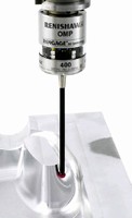 Created specifically for small machining centers, the innovative OMP400 optical probe measures only 40 mm in diameter and 50 mm in length, combining miniaturization of the highly successful OMP40 probe with new advances in strain gauge technology. The probe's diminutive size allows small machine users for the first time to benefit from the high accuracy of strain gauge technology. The innovative probe allows operators of small machining centers to reduce set-up times, scrap and fixture costs, improve process control with high accuracy on-machine measurement, and realize "done in one" production efficiencies. The OMP400 is suitable for use on machines with short Z-axis travel and spindles as small as HSK32.
Offering an unrivaled combination of size, accuracy, reliability and robustness, the OMP400 can bring the benefits of probing to many high accuracy applications. Using Renishaw's advanced strain gauge technology, the OMP400 can achieve far greater levels of accuracy than possible from a standard mechanical probe, making it suitable for a range of applications where high precision measurement is a must.
Strain gauges allow the probe to trigger at much lower and highly consistent contact forces, resulting in less bending of the stylus and negligible pre-travel for greater accuracy. First seen on the MP700 spindle-probe, strain gauge technology is unique to Renishaw and delivers superior probe repeatability.
Reduced in size but not in robustness, the OMP400 is sealed to IPX8 and built to withstand the harshest machine tool environments, giving greater resistance to stylus overtravels and shocks caused by tool changers. Battery life provides up to 50 hours of continuous use.
The probe features Renishaw's existing transmission system and a new 'modulated' method, offering improved resistance to optical interference. This allows the OMP400 to be partnered with either existing OMM and OMI receiver, or the new OMI-2 integrated receiver and interface. It is ideal for retrofitting to existing machines, or as a simple upgrade for existing probe users.
Alibre Design Version 9 Released
Alibre Inc. released the newest version of its signature 3D parametric solid modeling software, Alibre Design 9.0. The latest version provides dramatic new functionality and ease-of-use enhancements, and an expanded API to satisfy development partners.
This release comes on the heels of the successful Alibre Design Xpress launch that has seen the company's user base grow by more than 30 times in six months. Alibre is now delivering more licenses of parametric solid modeling software per month than any other company in the market.
The latest release of Alibre Design provides a host of new capabilities, including the following:
GeForce 7 Series GPU to AGP Users
NVIDIA Corporation announced the new NVIDIA® GeForce 7800 GS graphics processing unit (GPU) for AGP-based systems. Boasting the feature set of the award-winning GeForce 7800 GPUs, the new GeForce 7800 GS GPU features advanced technologies including:
• Support for Microsoft® DirectX® 9.0 Shader Model 3.0 and high dynamic-range (HDR) rendering for advanced lighting effects, as well as transparency adaptive antialiasing—to deliver ultra-realistic visual quality in the latest games.
• The third-generation NVIDIA architecture optimized for Microsoft® Windows Vista™—designed to give users the best possible experience with the 3D graphical user interface in the upcoming operating system (OS)
• NVIDIA PureVideo™ technology—the combination of high-definition video processors and software delivers unprecedented picture clarity, smooth video, accurate color, and precise image scaling for the playback of video content.
Monday, February 06, 2006
Compressed 3D Models Still Look Great with VizUp 2
VizUp Technology unveils a new polygon reduction system that enables anyone to reduce the number of polygons in a complex 3D model up to 90% without much effect on its visual quality.
VizUp is an ad-hoc polygon reduction system that enables you to reduce the number of polygons in a complex 3D model while retaining the quality and appearance of the original. The end result of the reduction is a 3D model with a well-balanced level of details and size, which is perfect for the use in virtual reality and real-time visualization systems. The process of reduction is extremely simple and doesn't require any advanced knowledge. VizUp automatically picks all necessary parameters without any manual interference on your side.
VizUp has a refreshingly uncomplicated user interface, which consists of the 3D viewer in the center and a toolbar with all commands and options ready at hand. Once you loaded a model, you can compress it with a single click on the Reduce button on the toolbar. VizUp performs the compression automatically. The best thing in it is that a model is compressed for all possible ratios at once. This means you can see the effect of any compression level instantly without having to restart polygon reduction each time for 10%, 20%, 30%, and other ratios. Another good thing about VizUp is its unique ability to retain the original look of a model. VizUp doesn't change the coordinates of the vertices and it results in minimal distortions during texture mapping even at high compression ratios. You can examine the result of reduction in 3D from different perspectives and in different visualization modes. This includes displaying a model as a set of textures, a set of smooth surfaces colored according to the material properties, as an object consisting of flat polygons, as a wireframe, or as a set of vertices.
Version 2 of VizUp builds on the success of the previous release that saw a high customer adoption in 2005 and received favorable comments and recommendations from customers like the one that belongs to Stuart Williams from Virtuality. "I have tried out several commercial polygon reduction tools in the past, and this is easily as good or better than them. It's extremely simple to use and the polygon reduction is great. Very useful for simplifying models made with nurbs or metaballs. It reduced a high-poly vrml model from 617kb to 115kb with practically no difference in appearance. I had to check the wireframe view to be sure of what I was seeing."
VizUp's Features at a Glance:
- High quality of complex model optimization;
- Extremely simple and user
-friendly;
- Optimization is performed automatically, no parameter tuning necessary;
- Decrease the number of polygons dramatically without loosing quality;
- Perform optimization only once
- simultaneously for all possible reduction ratios;
- Visual control for model tuning during the process of optimization;
- Built-in 3D viewer is intuitive and lets you examine your model;
- File structure stays the same
- comments, text format, etc. do not change;
- Supports VRML 2.0/97 file format.
Right Angle Motor Cable Adapters
For those applications where you need to squeeze a NEMA 17 or NEMA 23 motor into a tight spot, QuickSilver Controls, Inc., now offers adapters for its 15 pin D shell motor connector (D15HD).  The QCI-D15HD-R1 routes the cable towards the motor shaft and the QCI-D15HD-R2 routes the cable away from the shaft.
Both adapters provide a height profile of 1 inch. Screws are included to secure the adapter to the motor.
Both adapters are designed to handle the full horsepower of either a SilverNugget N2 or SilverDust D2 servo controller/driver including both motor and encoder feedback signals.
Friday, February 03, 2006
Zero-Z Short Toolholder Offers Unmatched Flexibility
REGO-FIX is proud to announce the release of its newest toolholder, the Zero-Z. Appropriately named for its machining capabilities, the flexible Zero-Z features an incredibly short projection, allowing for more z-axis stroke and greater work piece size.
Ideal for multiplex turning machines and small vertical machining centers, the Zero-Z offers improved surface finish, unsurpassed accuracy and complete tool rigidity. The toolholder's unique design features a flush collet nut, whereby tool overhang is virtually eliminated. Like all REGO-FIX toolholders, the Zero-Z is pre-balanced to G2.5 at 22,000 rpm. For added clamping force, the Zero-Z comes standard with REGO-FIX'S Hi-Q external clamping nut.
Currently, the Zero-Z is compatible with the CAT 40 taper and REGO-FIX's ER 32 series of collets. The ER series is the most widely used and accepted clamping system in the world, offering two levels of precision - standard and ultra-precision (UP). Offered in standard and metric sizes, the ER 32 collets can accurately clamp tool shanks ranging from 1.0 mm (0.0394") up to 20.0 mm (0.7874"). The Zero-Z holder in the ER series is compatible with both precision levels.
Additionally, the Zero-Z can be used with REGO-FIX's tapping collets for a variety of tapping applications. These collets are available in rigid tapping and axially compensating tapping styles.
Modular CNC Package supports high-speed machining
New Operator Console with Integrated Controller/Amplifier is an Easy to Setup, Cost Effective, Open Architecture Solution for CNC Machines.
The Advantage 900 CNC package combines a sleek operator console with a four, six or eight-axis controller/amplifier specifically designed to meet next-generation CNC control requirements. The 900 CNC leverages the capabilities of the operator interface PC, while utilizing a real-time DSP to handle the motion related tasks of the CNC machine. This combination delivers a cost effective PC front end with true real-time servo performance at the servo.
The integrated digital amplifier and control streamlines the manufacturing process, which significantly reduces the cost to the end user.
Additional cost savings flow to the consumer with a greatly reduced installation process, which requires less wiring, space and setup time.
Because the 900 CNC is modular, it allows an infinite number of machine configurations.
The 900 CNC supports high-speed machining, dynamic multi-block segmented look-ahead for path fidelity at any speed, forward and inverse kinematics for non-traditional mechanical configurations, 5-axis programming capability, and lead screw and backlash compensation.
The 900 CNC features a 15-inch LCD screen, customizable operator controls, wireless remote pendant with user-definable function keys, an embedded industrial PC, the new user configurable 5.0 HMI NC software, and the NC Autopilot quick setup tool, all in a slim line design with four, six, or eight axis Geo Brick controller/amplifier combination. Integration and connectivity between the operator console and the smart servo amplifier utilizes a single USB2.0 interface cable. To complete a CNC control system with the 900 CNC, the requirements are the motors and a minimum amount of field wiring.
A CNC Autopilot setup utility simplifies integration by automatically creating the configuration files for a particular machine. An Autotune software feature speeds the user through motor setup. The NC5.0 GUI was designed using the PMAC HMI program, providing the end user with an easy-to-use customize the NC software interface for specific applications.
The PMAC NC 5.0 for Windows software executes standards RS274 G-Code programs and has a wealth of diagnostic screens and tools.
Thursday, February 02, 2006
A New Way to Help Computers Recognize Patterns
Researchers have found a way to boost the development of pattern recognition software by taking a different approach from that used by most experts in the field. This work may impact research in areas as diverse as genetics, economics, climate modeling, and neuroscience.
Researchers at Ohio State University have found a way to boost the development of pattern recognition software by taking a different approach from that used by most experts in the field. This work may impact research in areas as diverse as genetics, economics, climate modeling, and neuroscience. Aleix Martinez, assistant professor of electrical and computer engineering at Ohio State, explained what all these areas of research have in common: pattern recognition.
He designs computer algorithms to replicate human vision, so he studies the patterns in shape and color that help us recognize objects, from apples to friendly faces. But much of today's research in other areas comes down to finding patterns in data -- identifying the common factors among people who develop a certain disease, for example.
The majority of pattern recognition algorithms in science and engineering today are derived from the same basic equation and employ the same methods, collectively called linear feature extraction, Martinez said. But the typical methods don't always give researchers the answers they want. That's why Martinez has developed a fast and easy test to find out in advance which algorithms are best in a particular circumstance.
"You can spend hours or weeks exploring a particular method, just to find out that it doesn’t work," he said. "Or you could use our test and find out right away if you shouldn't waste your time with a particular approach." The research grew out of the frustration that Martinez and his colleagues felt in the university's Computational Biology and Cognitive Science Laboratory, when linear algorithms worked well in some applications, but not others.
In the journal IEEE Transactions on Pattern Analysis and Machine Intelligence, he and doctoral student Manil Zhu described the test they developed, which rates how well a particular pattern recognition algorithm will work for a given application. Along the way, they discovered what happens to scientific data when researchers use a less-than-ideal algorithm: They don't necessarily get the wrong answer, but they do get unnecessary information along with the answer, which adds to the problem.
He gave an example.
"Let’s say you are trying to understand why some patients have a disease. And you have certain variables, which could be the type of food they eat, what they drink, amount of exercise they take, and where they live. And you want to find out which variables are most important to their developing that disease. You may run an algorithm and find that two variables -- say, the amount of exercise and where they live -- most influence whether they get the disease. But it may turn out that one of those variables is not necessary. So your answer isn't totally wrong, but a smaller set of variables would have worked better," he said. "The problem is that such errors may contribute to the incorrect classification of future observations."
Martinez and Zhu tested machine vision algorithms using two databases, one of objects such as apples and pears, and another database of faces with different expressions. The two tasks--sorting objects and identifying expressions--are sufficiently different that an algorithm could potentially be good at doing one but not at the other. The test rates algorithms on a scale from zero to one. The closer the score is to zero, the better the algorithm.
The test worked: An algorithm that received a score of 0.2 for sorting faces was right 98 percent of the time. That same algorithm scored 0.34 for sorting objects, and was right only 70 percent of the time when performing that task. Another algorithm scored 0.68 and sorted objects correctly only 33 percent of the time.
"So a score like 0.68 means 'don't waste your time,'" Martinez said. "You don't have to go to the trouble to run it and find out that it's wrong two-thirds of the time."
He hopes that researchers across a broad range of disciplines will try out this new test. His team has already started using it to optimize the algorithms they use to study language and cancer genetics.
Nastran FEA Modeler Extends the User Base
Noran Engineering, Inc. (NEi) a leading developer of Nastran Finite Element Analysis (FEA) software used extensively for product design and simulation, announced that its release of its NEiModeler V9.1 will extend both ends of the user spectrum for the product by providing special features for new and experienced users.
This release is part of a product strategy of allowing easier adoption of FEA technology by new users, while supporting the most sophisticated users with advanced tools. The overall objective is a smooth, continuous pathway to increasing skill levels of analysis and simulation in virtual product development.
FEA software is being adopted at increasing rates as companies seek to lower product development costs without compromising quality or forfeiting innovation. NEiNastran Modeler V9.1 addresses these new users by providing both comprehensive CAD geometry transfer and FEA model creation capabilities in a flexible, familiar, native Windows environment incorporating the latest generation Microsoft technology.
Not only can the NEiModeler accept all major 3D CAD files (e.g. Solid Edge V18, CATIA V5, SolidWorks, Pro/Engineer, AutoCAD Inventor) but full 3D model creation for analysis is possible, even for those without 3D systems -- by incorporating the two most widely used and regarded geometry engines, Parasolids and ACIS.
For experienced FE analysts, sophisticated features have been added in meshing, spot weld simulation, customization, and automation functions. These include, a new Quadrilateral Element meshing option for critical boundaries and stress raisers, a Nastran Spot Weld Element for sheet metal, a Macro driven program file for automating repetitive tasks, and a fully integrated BASIC development environment for customizing post-processing functions.


