Romax Technology Ltd has announced the launch of its latest software package, RomaxDesigner R12.3, a package that promises to save even more time and money for transmission and driveline design and development teams around the world - allowing them to take their products to market faster.
This new software modelling tool allows engineering teams to design systems and test them before they even leave the computer screen, negating the need for expensive 'physical' testing and allowing multiple virtual product tests to be conducted accurately and effectively in record time.
The software package comes with a host of upgrades and new features designed to improve flexibility for teams. It increases design control by incorporating analysis into the first stages of the design process, while at the same time boasting greater connectivity with packages such as Abaqus and Ansys - helping information exchange and the flow of data.
Also, for the first time, the software package has been localised, offering English and Chinese language options and allows users to work within a variety of international gearings and bearings standards.
"By allowing virtual testing, our new software modelling tool is helping to speed up the evolution of transmission and driveline systems, as well as reducing costs and increasing companies' competitive advantage in the market place," explains Andy Poon, Romax Technology software manager.
"This upgrade has created an 'all-in-one' tool for engineering teams that will allow them to realise their designs with increased ease and flexibility and enable them to stretch the boundaries of their R&D budgets."
Tuesday, January 31, 2006
Virtual Product Design System for Transmission and Drivelines
Intelligent motion controller via CANBus or serial port
ION(TM) DC Brush Drive - this fully enclosed, compact module is the second in PMD's NEW family of high performance motion control drives providing network connectivity, power amplification and advanced motion control features in a rugged, easy to use package. ION is available for DC brush, brushless DC and microstepping motors, and is ideal for medical, scientific, semiconductor, industrial, robotic and general automation applications.
Based on PMD's high performance Magellan(TM) Motion Processor, the ION DC Brush Drive provides high-performance, low cost distributed control in an asynchronous serial network (RS485) version or a CANBus network version. Multiple ION modules (up to 127) can be connected on a single network. ION provides an output capability of up to 15 amps peak, and 500 W at 56 volts. Other features include hardware performance trace, on-the-fly profile changes, and PLC style inputs and outputs.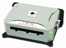
President and CEO, Chuck Lewin says, "The move toward distributed motion controllers has been driven by cost. A multi-axis motion card with separate amplifiers is substantially more expensive than multiple single-axis intelligent modules. The reduction in wiring in that sense actually comes for free, because it is absolutely not necessarily to justify the move to a serial network."
ION can be programmed using Pro-Motion®, a Windows(TM)-based exerciser which allows quick and easy drive set up or C-Motion® and VB-Motion(TM) software libraries which let users to develop their own applications in C/C++ or Visual Basic.
The ION Drive is CE marked and RoHS compliant. Prices start at $223 in OEM quantities.
Monday, January 30, 2006
Thick Turret Tooling
Mate Ultra Tec and Ultra XT Tooling combine both long life design and interchangeability features for maximum performance and cost effective punching. The tooling has many unique design features for achieving superior performance in punching holes including quick setup, easy installation, faster maintenance, and interchangeability with other suppliers' tools and tool systems. Included are Slug Free® dies, an exclusive Mate feature that clears the punched slug with every cycle. This eliminates slug pulling, extends tool life, improves piece part quality and reduces scrap.
Mate Ultra Tec and Ultra XT Thick Turret tooling are available for Amada, Finn-Power, Murata Wiedemann, Euromac, Nisshinbo, Strippit and all other punch presses using thick turret style tooling.
Friday, January 27, 2006
CAMWorks 2006EX Featuring New Multiaxis Machining Mod
TekSoft, an industry leader in developing advanced manufacturing software, has released CAMWorks 2006EX featuring a new module for Multiaxis Machining that allows a wide variety of shops and manufacturing facilities to take advantage of 4/5-Axis machines that provide greater productivity, equipment flexibility and quality.
CAMWorks 4/5-Axis simultaneous machining allows the user to create toolpaths across complex shapes that could not be machined on 3-Axis machines. This includes high-performance automotive port finishing, impellers, turbine blades, cutting tools, 5-Axis trimming, and undercut machining in mold and die making. CAMWorks 4-Axis simultaneous machining is designed for complex rotary applications such as camshafts, extrusion screws and blades.
After being acquired by Geometric Software Solutions Co. Ltd. (GSSL) in January 2005, TekSoft implemented an aggressive product development schedule that leverages GSSL's world leading CAD/CAM/CAE/PDM software expertise to enhance TekSoft's technology offerings. CAMWorks 2006EX, which is the third major release in less than a year, reflects the combined strengths of TekSoft and GSSL by delivering a powerful set of over 50 new performance enhancements, improvements to the intuitive user interface to make CAMWorks even easier to use, plus features and cutting strategies to meet the machining requirements of diverse applications.
Significant performance enhancements include:
New features and cutting strategies in CAMWorks 2006EX include:
According to Mike Coleman, President and CEO of TekSoft, "CAMWorks 2006EX is the result of leveraging a strong, shared foundation in CAM technology that allows TekSoft to use the combined resources of TekSoft and GSSL to increase its innovative edge in delivering CAM solutions and compete more successfully in the expanding market for solids machining. We will continue to act aggressively to improve our product to meet the needs of the mold making and machining industries."
Thursday, January 26, 2006
Moldflow Plastics Insight 6.0
Moldflow Corporation announced release 6.0 of Moldflow Plastics Insight® (MPI®), the industry’s most powerful and widely used plastics design analysis software.
MPI 6.0 delivers new technologies and key enhancements that help users work more efficiently, significantly reduce solution time, interact better with CAD, structural analysis and other Moldflow applications, and better understand and communicate analysis results.
Two new technologies in MPI 6.0 bring significant breakthroughs for 3D filling and warpage applications. The new coupled 3D Flow solver is up to eight times faster, and renders more accurate temperature and shear heating calculations, new capabilities to predict air traps and to simulate gas penetration in 1D beam elements, and the first-of-its-kind capability to simulate jetting phenomena. Similarly, new 3D Warp solver technology delivers results up to 35 times faster.
Other key features:
• MORE EFFICIENT, PANEL-BASED USER INTERFACE – Reorganized display reduces screen clutter and allows more efficient workflow for most tasks with a new Tools panel and Toolbox, consolidated Project and Study Tasks panel, and single log window that consolidates most textual outputs.
• IMPROVED PRODUCT INTEGRATION - Export Part/Runner/Cooling model to CAD via IGES format, improved interfaces to ABAQUS® and ANSYS®, a new interface to LS-DYNA™, plus new capabilities to exchange design-through-manufacturing data between Moldflow Manufacturing Solutions and Design Analysis Solutions products. The improved integration between MPI and industry standard structural integration programs allows designers of high performance plastic applications to more accurately account for the effects of processing on the performance of injection molded plastic parts when subject to service loading.
• STREAMLINED DIAGNOSTIC AND COMMUNICATION TOOLS – Systematically validate mesh quality with directed diagnostics navigation. Generate reports in Microsoft® Word® or PowerPoint® formats, in addition to HTML format. Share information with a distributed design-through-manufacturing team by exporting Moldflow results files and creating comparison criteria files for viewing in the Moldflow Communicator utility.
• MORE INFORMATIVE RESULT DISPLAYS – Isolate warpage due to unbalanced cooling, non-uniform shrinkage and fiber orientation in 3D Warp, view mold internal temperature distributions in 3D Cool, see the plastic re-melt zone in 3D Overmolding, capture changes in the flow front due to jetting in 3D Flow, visualize the Von Mises stresses on the surface of the core in Core Shift, and isolate warpage due to corner effects for Midplane and Fusion Warp analyses.Moldflow Corporation is the leading global provider of design through manufacturing solutions for the plastics injection molding industry. Moldflow’s products and services allow companies to address part and mold design issues at the earliest stage and maximize productivity and profitability on the manufacturing floor.
Tuesday, January 24, 2006
3DLabs Wildcat Realizm 800 & 500 For HP
3Dlabs Inc., Ltd. announced that the Wildcat® Realizm™ PCI Express-based family of professional graphics accelerators has been selected for the HP Tested & Certified graphics program.
Wildcat Realizm 800, previously certified in the HP xw8200 Workstation, is now certified for the HP xw9300 Workstation. The mid-range, high-performance Wildcat Realizm 500 is now certified for the HP xw6200, xw8200 and xw9300 workstations. 3Dlabs is a wholly owned subsidiary of Creative Technology Ltd.
HP xw6200 and xw8200 workstations are equipped with a choice of single or dual Intel Xeon processors. HP xw9300 workstations offer dual single- and dual-core AMD Opteron processors. All configurations support Microsoft Windows XP Professional or Red Hat Enterprise Linux Workstation 3 operating systems.
CATIA V5 Helps Bicycle Maker Accelerate Innovation
Pacific Cycle, Inc., which includes such high-performance brands as GT Bicycles and Mongoose as well as the household names Roadmaster and Schwinn, employs some of the industry’s most innovative design minds at three US sites in Wisconsin, Colorado and California. But finding a Product Lifecycle Management solution that enabled these designers to create without limits – and that facilitated the translation of their brainstorms into actual manufactured products – was a challenge.
"Other packages we used in the past never had the capabilities to take the designs to the limits of the designers’ imagination," explained Forrest Yelverton, Director of Engineering and the company’s lead designer. "We were always limited not by our imaginations, but by the constraints of our tools."Freeing designers to create anything they could imagine was only half the challenge, however. Building what they imagined was the other half, and some of what they designed was so difficult to convey to the company’s overseas manufacturers that the mechanisms rarely worked without costly and time-consuming back-and-forth trial and error. "Our suppliers couldn’t see how it worked, so they couldn’t accurately envision how to build it," Yelverton said.
Improved Collaboration, Smoother Manufacturing
Since adopting CATIA V5 from Dassault Systèmes and IBM, both challenges have been eliminated. Pacific Cycle now has a PLM authoring system as limitless as the imaginations of its designers, plus the ability to animate its designs for the overseas factories that build them. The system also facilitates collaboration among the company’s three dispersed design teams.Yelverton, who designed the bicycles used by the 1996 US Olympic team, among others, particularly appreciates the fact that CATIA V5 allows designers to move effortlessly from wireframe to surfacing or solids. Because designers don’t have to move in and out of their design to switch from one mode to another, their creative mental flow continues uninterrupted. The process also saves time. "CATIA V5 has that ability to operate in hybrid mode, which no other CAD package offered," he said. "It’s extremely powerful." The powerful animation capabilities in CATIA V5 Kinematics, a module that Pacific Cycle chose to add to its basic MD1 configuration, also helps the designers to clearly communicate their intent to the companies thatmanufacture the components and bicycles. The factories are located primarily in Asia Pacific.
Fewer Errors, Better Value
"It’s extremely helpful that we can not only send them a model of the thing we want, but also our animations of how assemblies go together, of how things might be machined to lower the cost,"Yelverton said. "Having them actually be able to see how things go together and function without having to explain all that makes it go a lot faster." Being able to clearly communicate design intent and design motion also helps to eliminate costly errors, Yelverton said. "Because our suppliers clearly understand what we’re going for, they can add their own expertise without worrying that they are destroying the functionality. That allows them to deliver the best value." But the true power of CATIA V5, Yelverton believes, is its ability to remove the traditional bounds on innovation. "We can have something up and on the screen and working in a day, which gives us more time to innovate. Best of all, it allows us to design to the limits of our minds’ abilities, rather than being constrained by the abilities of the tool."
Although Pacific Cycle has not made formal measurements, "it’s apparent the investment has more than paid for itself," Yelverton said. "I know the bean counters are comfortable with the return because they have allowed us to continue to invest." The IBM PLM Express Portfolio is designed to be scalable, allowing companies to acquire advanced PLM functionality at a price they can afford and expand their capabilities as they grow.
Sunday, January 22, 2006
Ultrasonic Sensors
Ultrasonic Sensors sensors offer simple digital programming, quick disconnect cables, potentiometer-free adjustability, and automatic temperature compensation for simple set-up and operation.
The 12mm series are UL listed, CSA certified and carry the CE mark. They feature a nickel-plated brass housing and provide IP65 protection for reliable operation in dusty or water-overspray application environments. Additionally, they provide 4-20mA/20-4mA and 0-10V/10-0V analog output, an adjustable sensing range from 50 - 400mm, response time of 50ms and resolution to 0.17mm.
Friday, January 20, 2006
Highly efficient 3D module for part unfolding
Bystronic will introduce the Bysoft software version 6.2.2 with a new, highly efficient integrated 3D module for part unfolding. This new module allows users to completely unfold three dimensional models from SAT, STEP and IGES formats. Through a direct interface, 3D models are taken over directly from SolidWorks® and Autodesk Inventor® into the Unfolder. Bend allowances can be readily assigned to the 3D bent part by way of selecting bending tools and placing them within the Unfolder. The 3D model can be unfolded to 2D and then easily imported into Bysoft, Bystronic's integrated cutting and bending software.
Bysoft software enables complete process optimization from file to part. It offers users advanced synchronization of press brake, laser and waterjet processes. Bybend, another integrated Bysoft software module, provides automatic bend deductions, tool selection, bending sequences and back gauge placements for press brake users. This feature permits visualization of the bending sequences as well as automation collision detection before the part is sent to the operator for processing. This software reduces set up time and the need for test bending.
Related Posts
Machining from STL files-Part 1 Machining from STL files-Part 2 Step NC end of g code-Part 1 Step NC end of g code-Part 2 Step NC end of g code-Part 3
Thursday, January 19, 2006
64-Bit Version-Pam-Crash Simulation
ESI Group of France announces the release of its PAM-CRASH Solver software for crash simulation for engineers on Microsoft Windows Compute Cluster Server (CCS) 2003. This announcement follows a successful demonstration of the powerful capabilities of the company's 64-bit Open Virtual Try-Out Space (VTOS) interface on a cluster of industry-standard hardware at the SUPERCOMPUTING 2005 tradeshow in Seattle on Nov. 15.
The software is ported to Windows Server 2003 x64 Edition and easily integrates with Microsoft Message Passing Interface and Job Scheduler technologies. Because the cluster increases the computing power, the solution offers a cost-effective approach to running resource-demanding CAE applications, like PAM-CRASH. This advantage allows engineers to work with very large virtual models (more than 4.5 million elements) that require more than 3 to 4 GB of memory, explains Jean-Louis Duval, Open VTOS Business Manager of ESI Group.
The Open VTOS is a proven engineering simulation environment initiated with PAM-CRASH, LS-DYNA, NASTRAN and RADIOSS software on Windows CCS 2003, and encompasses Visual Environment and all ESI Group's simulation software. "This version will allow our customers to benefit from the performance of the DMP [distributed memory processing] version of PAM-CRASH on clusters of industry-standard 64-bit hardware," adds Vincent Chaillou, President and Software Operations Chief Operating Officer of ESI Group.
"We understand that the availability of 64-bit applications from software vendors such as ESI is critical in helping our mainstream customers be able to easily deploy, manage, and use Windows Compute Cluster Server 2003," says Kyril Faenov, Director of High-Performance Computing for Microsoft.
Tuesday, January 17, 2006
New 12 Volt DC Gearmotor
Midwest Motion Products of Watertown, Minnesota, is pleased to announce the release of a new DC Gear Motor, the Model No. MMP-TM55-24V GPk52-022. Accepting any 24 Volt DC source, including battery power, this robust Gear Motor measures just 2.14" in Diameter, by 7.25" long, and has a keyed output shaft of 12mm diameter by 25mm long. Easy mounting is accomplished with 4 "face mount" M5 threaded holes, equally spaced on a 40mm Diameter B.C.
The output of the gearmotor is rated for 2.5 Nm continuous torque, at 205 RPM, and 9.0 Nm Peak. Despite it's compact size and weight, the Motor is an efficient design, requiring just 3.6 Ampere at 24 Volts DC to generate its Full Load Output Torque. Optional 12 & 36 Volt windings are available.This unique design is rated at an "IP 54" protection level for operation in harsh environments.Samples are available FROM STOCK for rapid prototyping needs.Typical options available from the company include Servo Motors with integral Optical Encoders, Failsafe Brakes, Analog Tachometers, and Planetary Gear heads, with standard ratios ranging from 3:1 to 450:1, and standard or low backlash precision gearing available.The company offers a variety of standard ancillary equipment including multi-axis drive and control configurations, DC power supplies, DC servomotors, PWM Servo Amplifiers, Motor Speed Controls, Linear Actuators and a wide variety of DC gear-motors. Custom Motor Shaft and mounting configurations are also available. Typical applications include Battery Operated Motors & E.V. drives, Medical, Mobility / Accessibility products, Robotics & Automation including Unmanned Guided Vehicles, Semiconductor Processing Equipment, Actuators, Packaging & Labeling Machines, Metalworking Machines, and many other applications requiring precise motion control.
Monday, January 16, 2006
Safe Metalworking Lubricant for Sawing Aluminum
Recommended for all metals and all types of machining, environmentally safe Accu-Lube LB4600 is non-staining, has low odor, and burns off during post heat-treat processes. Base oil is made from 9 renewable vegetable sources, which act as carrier for lubricity package. Non-toxic, biodegradable products has mild, grape odor and is purple in color. Only 1-2 oz of lubricant is needed per nozzle for 8-hr shift.
ITW ROCOL North America is announcing the launch of Accu-Lube LB-4600, a new metalworking lubricant specifically designed to meet the needs of aluminum extruders sawing aluminum, prior to post heat treating.
Accu-Lube LB-4600 is a natural environmentally safe metalworking oil recommended for general use for all metals and all types of machining. This lubricant unique chemistry matches superior lubricity requirements for sawing and machining of aluminum. It is
non-staining, has low odor and easily burns off during post heat-treat processes. It is environmentally safe, non-toxic, and biodegradable.
The base oil of the Accu-Lube LB-4600 is made from nine renewable, vegetable resources. These esters are economical and act as a carrier for the lubricity package. The LB-4600 has a mild, grape odor and is purple in color.
Accu-Lube creates safer working conditions, longer blade life, less machine maintenance and enables long term cost savings. The main advantage of using Accu-Lube versus coolants is that you use much less Accu-Lube lubricant. Accu-Lube also manufactures a complete line of applicators. Accu-Lube applicators apply only 1-2 ounces of lubricant per nozzle for an eight-hour shift. Another main advantage of using Accu-Lube applicators is that you never have to stop production to recharge the coolant - There is no expense for labor and machine downtime.
Friday, January 13, 2006
Delcam ArtCAM Review
While CAD systems are excellent at creating highly regulated forms and features, there are many occasions when you need to integrate more aesthetic elements into your normal product designs. Delcam's ArtCAM system allows you to create such forms using the basic medium of any design, the sketch, and create three-dimensional models which can then be incorporated into a regular CAD model or machined straight from the system.
Its working methodology is to make the creation of such forms easy and without the overheads of many engineering and design systems by removing the mathematics usually involved. The system is mostly aimed at engravers and signmakers, but still has advantages for engineers and designers. The interface is graphically led and anyone picking up the system for the first time should be able to jump straight in.
In use
The first stage is to create the initial sketch. This can be done in two ways, either by importing a bitmap type image (Jpg, Tiff or BMP) or using vector formats (such as EPS, AI or DXF). The system also includes all manner of sketching and drawing tools. Although these are not as comprehensive as tools such as Photoshop or Adobe Illustrator, they should provide you with enough to get started.
The next stage is the basis of the whole process. To define the 3D properties of each section within a sketch or model, you need to define the boundaries, its extrusion profile (such as concave/convex) and the height. It may sound complex but the process is almost effortless. These sections can be built up in layers to create precisely the form you require. If you should be using bitmap images, the system also includes tools that allow you to convert grey scale images into 3D models (with white being the highest point). This uses the range between black and white to define the z level of the model areas. Although it may sound ideal, the process requires some thought as shadows can wreak havoc with models generated from photographs. However, in experienced hands (and with a copy of Photoshop) truly remarkable results can be achieved.
Editing tools
Although the raw creation tools are fantastic, you're probably going to need some form of 3D editing tools to perfect your model. The Interactive Modelling tools are very similar to those found within many 2D paint packages and include smudge, deposit, carve and an eraser. Perhaps the best is the smoothing tool which allows you to smooth areas of a model according to the surrounding area. This is also excellent for repairing errors in scanned data. All of the tools use very similar methods to 2D painting, but instead of laying colour they deposit or remove 3D material from the model. Additionally, pressure sensitive tablets can be used should you have access to one.
One of the most popular applications for this system is the creation of small moulds for the production of jewellery and the system also includes inverting tools which allow you to create cavities of sculpted parts with ease. On this side of things, ArtCAM also has scaling tools, which allow you to not only scale as normal, but according to a specific volume within a mould - very handy when working with precious metals in jewellery or when exact weights of, for example, confectionery must be specified.
In addition to the vector-based and interactive modelling, you can also add textures to portions of the model. In this mode, you can use one of the range of textures supplied, or create your own pattern and apply it to the required sections. Again, this may seem a frivolous feature, but consider adding texture detail to automotive interior trim. This process would require additional stages in the manufacture of the mould tool, which could potentially be made much easier.
Machining functions
As this system is from Delcam, you would expect some type of CNC code generation tools and ArtCAM doesn't disappoint. From within the system as standard, you have the ability to create fairly complex and accurate 3D machining tool-paths which can then be used on whatever hardware you have in place. Should you require further capabilities, or be looking at ArtCAM as an extension of your existing CAD/CAM tools, then that's also a possibility. Obviously Delcam would love for everyone to have a copy of ArtCAM as a supplement to its core modelling system, PowerShape. Using it alongside PowerShape means that you can take your ArtCAM textured and sculpted models and incorporate them into the "production" CAD model, which can then be used as the basis for the mould tool.
The machining functions with ArtCAM follow the common working process, and you first define what you need to machine (which can be done using Vectors as limiting boundaries). You then choose a tool (from the supplied library or a custom define stock of cutters), then it's time for the maximum cut depth and the speeds and feeds. The system subsequently calculates the cutting path, which can then be simulated to check surface finish and quality.
In conclusion
Many readers looking at this review may be forgiven for thinking "What?", but unless you have an application for it, you may never appreciate ArtCAM's potential benefits. The capabilities and processes it covers would probably be carried out by a third party, so bringing these in house gives you a far greater amount of both control and security.
As it stands, ArtCAM occupies a niche within a much larger CAD/CAM industry and does so comprehensively. The functions within the system are perhaps unique and the system does look like a great deal of fun to use. Many may scoff at the vaguely "hobbyist" style interface and general look and feel, but the functions beneath its teddy-bear fixated UI, more than justify its place in this pages. If you're looking for a system which allows you to incorporate artistic 3D relief work into more mainstream CAD models, then look no further.
Thursday, January 12, 2006
VERICUT 6-New features
CGTech will showcase VERICUT® 6 CNC machine simulation and optimization software in booth 2628 at the WESTEC Advanced Productivity Exhibition, March 27 through March 30, 2006 in Los Angeles CA.
VERICUT 6 features several enhancements designed to increase the ability of manufacturing engineers to simulate the entire CNC machining process in order to produce better results and reduce the time spent in the programming and machining cycle. New features include:
- the ability to view and configure multiple setups in a single session.
- the capability to simulate machines with multiple synchronized tools, spindles and auxiliary attachments.
- a redesigned tool manager that simplifies NC program optimization.
- an enhanced Model Export option that now exports in-process "cut models" as native CATIA V5, ACIS SAT, and STEP models.
- the ability to create CNC probe programs and inspection sequences.
Wednesday, January 11, 2006
RFID System For Tracking and Control
Combining read/write module and miniature ID tag that provides data transmission, RFID System generates 125 kHz electromagnetic field and is designed for closed-loop manufacturing applications. 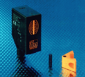 Measuring 55 x 24 x 41 mm, read/write module includes control interface, reader, and antenna. Unit exchanges data with re-usable ID tag at distance of 20 mm and can be mounted to pallets and workpiece carriers. Tag's 15-bit data can be read at travel speeds up to 0.5 m/s.
Reliable read/write technology, flexible mounting, and universal connectivity enable the ifm RFID system to be applied in industrial process control. The read/write module combines three components in one - a control interface, reader and antenna - that measures only 55 x 24 x 41mm.
The module exchanges data with a re-usable ID tag at a distance of 20 mm. The module stores transmission errors that can be retrieved for a targeted fault analysis. The tag can be directly mounted to pallets and workpiece carriers, or the tag can be inserted into ifm's miniature tag fixture.
The system generates a 125 kHz electromagnetic field for reading and writing data. The electromagnetic field emitted by the antenna induces voltage in the passive ID tag. This activates the ID tag that returns its code. The tag's 15-bit data is reliably read at travel speeds of up to 0.5 m/s.
Electrical connection is made directly to the AS-i network via an M12 connector. AS-i's design flexibility makes RFID implementation simple by eliminating the need for a separate control interface for each module. AS-i enables the connection of up to 31 read/write modules to the system.
ifm's RFID system connects to all common PLCs and industrial bus systems. The system features easy configuration and allows direct access to the data without the need for complicated software.
Tuesday, January 10, 2006
Contex-New Family of 3D Printers, Flatbed Scanner
At the Graphics of the Americas Conference and ExpoHerndon, Virginia, January 1, 2006, Contex unveiled its first line of 3D printers, enabling organizations to quickly and afford-ably create physical 3D models in office environments.
Contex will be demonstrating both the COPYmate 18 Flatbed Scanner with iJET Technology for direct connection to a printer for true Scan-to-print functionality and the new DESIGNmate Cx Color 3D Printer at the upcoming Graphics of the Americas Conference in Miami Beach, Florida. The event will take place on February 3-5, 2006 at the Miami Beach Convention Center and the Contex exhibition location is Booth #1776.
3D printers build physical models of real-world objects, such as engine parts, buildings, and landscapes. Engineers use these physical representations of electronic design concepts to communicate more effectively with customers, partners, and suppliers.
Applications include concept models, presentation models, functional testing, Finite Element Analysis (FEA), sales presentations, and market research on style, color, and packaging options. 3D printing is widely used in engineering markets including computer-aided design (CAD); geographic information systems (GIS); and architecture, engineering and construction (AEC).
Contex DESIGNmate Cx produces high-definition (600 x 540 dpi), full-color 3D models, eliminating the week long waiting period for custom fabricated prototypes. Superior inkjet printing technology creates parts with crisply defined features, enhanced accuracy, and precise 24-bit color.
Contex scanning technology is a manufacturer of 3D printers, wide-format color and monochrome scanners as well as expert developers of advanced scanning and copying software for these products.
Monday, January 09, 2006
Motion Controller Module acts as PCI-bus
Suited for stepper and servo motors, MCI-0410 positioning system links and enables motor/driver connectivity to controller. Programmable 4-axis PCI-bus controller module is controlled by MPG2031 pulse generator chip, which carries out PCI-bus operation and oversees all programmed commands. Features include Z-phase counting and various signal and encoder/sensor input keys, standard clock of 3.2768 MHz, output pulse rate of 0.1-1,638,400 Hz, and set pulses from 0-16,777,215.
The MCI-0410 is an ultra high-speed programmable card that is designed to link and enable motor/driver connectivity to a simplified controller without the time-consuming need for designers to learn a new write-up language or familiarize themselves with the latest motion control technology not yet practiced in majority within today's fast-pace industry. The card's design flexibility is controlled by Nyden's own Pulse Generator Chip, the MPG2031, which is included to carry out all facets of PCI-Bus Operation and oversee the smoothness of all programmed commands set forth by the engineer. Furthermore, its functions include ensuring that the running compliancy of the four axis motors (of either stepper or servo variety) operate proportionally or independently, and that the complete equipment hookup easily scales motion profiles during the stages of Point-to-Point (PTP) positioning, Linear positioning, Speed, Home Search, Triangular and Trapezoidal.
Data Gateway enables serial to WLAN connections
Dual-port ADAM-4570W acts as data gateway between RS-232/422/485 and 802.11b wireless LAN (WLAN) interfaces. With support for 802.11b, WLAN ad-hoc, and infrastructure modes, functionally transparent unit brings remote management and data accessibility to RS-232/422/485 devices that cannot connect to Wireless Ethernet network. Transmission speeds are rated to 230 kbps, with auto-reconnections, surge protection, and automatic RS-485 data flow control.
Friday, January 06, 2006
COSIMIR PLC-MECHATRONIC SYSTEM
3D Simulation Tool for Practical PLC Training
COSIMIR PLC is the new PC-based 3D simulation system featuring various industrial processes designed as a training aid for industrial automation classes. Features include:
- Students can simulate and control individual production processes
- Errors in student programs can be found without physically building any projects
- Instructors can introduce realistic faults in the simulation to sharpen student's troubleshooting skills
- Exercises involving sequence of operations are included
- Optional EasyPort accessory allows software to interface with external training hardware
An embedded logic device can control simulated processes including sorting, pick and place, testing and processing with a rotary index table.
more…Thursday, January 05, 2006
Basic Power Supply Design
For the purpose of this design, I am assuming that the user is going to use one of the Gecko drivers (G201 or G210).
In order to size the components, I will use values that I have used in the past. First is the voltage and current for the stepper motors. I used Superior Electric stepper motors model number KLM091f13. The voltage is 1.26 volts DC. The current is 6.6 amps.
At this point, I can calculate the desired power supply voltage. You want to make the power supply voltage at a minimum to be about 20 times the DC voltage rating on the stepper motors (1.26 VDC * 20 = 25.2 VDC) . The maximum voltage should be no more than 25 times the voltage (31.5 VDC). Note the minimum DC voltage for the Gecko drive is 24 VDC.
Once you have established the desired DC voltage, you can calculate the transformer secondary voltage. For my design, I used a transformer from Plitron Manufacturing Inc. In Toronto Canada. Plitro transformers are all custom made and can come in a wide variety of voltages.
To calculate the desired transformer voltage divide the desired power supply voltage by 1.4. Example ( 28 VDC / 1.4 = 20 VAC).
The last step is to calculate the desired transformer current and Volt amp (VA) rating. Three stepper motors rated at 6.6 amps would equal a total of 19.8 amps. In actuality, the value should never exceed about 67% of the total or in this case about 13.26 amps. Transformer are usually rated in Volt/amp values (20 * 13.26 = 265.32 VA). If you look up the transformer that I used from Plitron ( part number 077015201 you would see that it was rated at 300 volt amps and 22 volts AC.
The next calculation would be for the size of the filter capacitor. Use the equation of
(C= (80,000 * I) / V)). C is the value in microfarads, I is the current and V is the voltage.
Example : C= (80,000 * 13.27) / 30)). 35,376 uf. My capacitors were rated at 21,500 uf.. In this case, I used two capacitors in parallel.
The next device to select would be the bridge rectifier. I selected a surplus bridge rectifier at 25 amps at 50 volts.
Your next step is to find out how you transformer is wired. The wiring diagram below shows the primary and secondary windings of the transformer that I used. Both the primary and secondary have two sets of windings. The primary could be wired for either 115 volts at 230 volts. The diagram shows the transformer primary windings wired in parallel for 115 volts AC.
The secondary has two sets of windings. Wire them in parallel to double the current.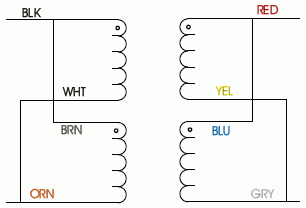
Bridge Rectifiers
What is a bridge rectifier? A bridge rectifier is a device that converts AC from a transformer into pulses of DC voltage. The DC voltage is then stored in a capacitor. The drawing on the left shows four diodes in a bridge configuration. The middle drawing shows a bridge rectifier with one corner cut off. This cut-off corner indicated that the terminal nearest to the corner is the positive or + terminal. The second picture shows another configuration for a bridge rectifier. In this case the bridge rectifier will be marked with a + symbol to indicate the positive terminal. The opposite (diagonal) terminal would then be the Negative (-) terminal. The other two terminals are for the output from the transformer secondary windings.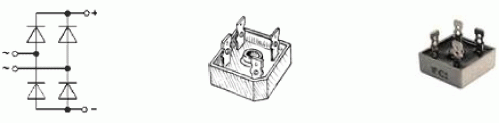
Capacitor
The next item that makes up a power supply is the storage capacitor. It is necessary to have a capacitor to store the voltage and filter out the pulses coming from the bridge rectifier. Below is a picture of a filter capacitor. Note that it has a working voltage and a surge voltage specified. Once you know the voltage for your power supply, then you can select the proper size (working voltage) capacitor. Note: this one has a capacity of 21,500micro farads (uf). For my power supply, I used two in parallel.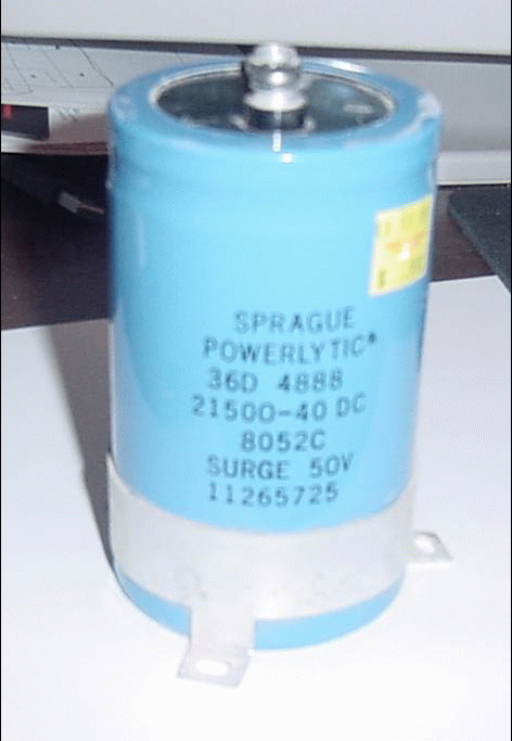
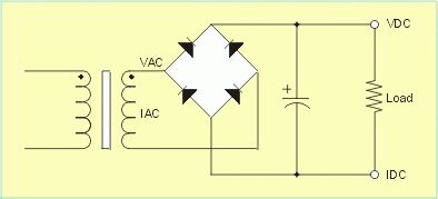
The picture above shows the proper connection from the secondary of the transformer to the bridge rectifier and the connection from the bridge rectifier to the filter capacitor.
The picture below shows the power supply section of the control box. Several additional items are required to complete the power supply. One is an on/off switch which should be rated to handle the current in the primary of the transformer. The current in the primary in this case should be under 5 amps. At the bottom left is a strain relief where the AC power cord is brought through the side of the control box. The other item is a couple of terminal strips.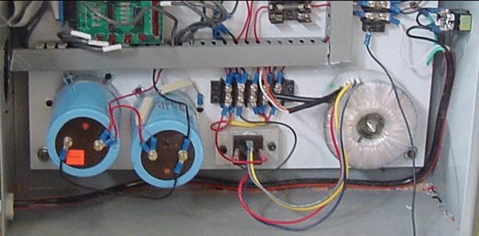
Wiring the Power Supply
First start by laying out the components. Drill and tap holes to mount the components. The transformer used a 3/8” bolt. I placed the bridge rectifier on a piece of aluminum to act a a heat
sink.
Wiring, start with the AC cord. I used a 14 amp 3 wire extension cord from my local Home Depot. Cut the receptacle end off. Then strip the insulation off by about 8”. Put a terminal lug on the end of the green wire (not shown below)and bolt it to a ground point on the back panel. Put terminal lugs on the end of the white. Attach the white to a terminal strip. Attach the end of the black wire to the on/off switch. From the other side of the on/off switch, run a wire to another terminal on the terminal switch. Locate the black and brown wire on the primary side of the transformer and install a terminal lug connecting both of them to one lug. Route the white an orange wire and attach the lug to the terminal strip opposite the white wire coming from the AC cord. Now find the black and brown wire and connect them together with a luge. Attach the black and brown wire to the same terminal as the wire that came from the on/off switch.
Now wire the secondary wires from the transformer to the bridge rectifier. You should have two
pairs (red and blue and yellow and grey). Find the + terminal on the bridge rectifier. The two
terminals adjacent to the + terminal are for the AC from the secondary from the transformer.
From the + terminal on the bridge rectifier, run a wire to the + terminal of the first capacitor. Run
another wire from the negative terminal on the bridge rectifier to the second terminal (-) on the
first capacitor. Now run two more wires from the first capacitor to the second capacitor (+ to + and - to -).
The following wires are not shown. From the negative side of one of the capacitors, run a wire to
a common ground terminal location. You will only want one ground point. All ground wires should be attached to this point. You will also want to run a wire from the + terminal on one of the capacitors to a terminal strip. Later you will run a wire from the terminal to the fuse block.
One item that is not shown is a circuit breaker. You can break the black wire that goes to the
on/off switch and add a circuit breaker. The other item that is not shown is the emergency off
switch. In the next file, I will add an EPO switch and a contractor.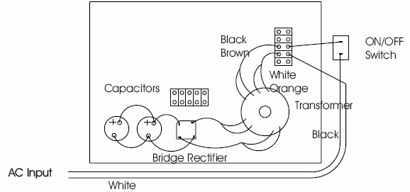
Related Posts
Wednesday, January 04, 2006
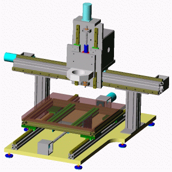
Building a CNC Router
What makes up a CNC router?
- Frame (aluminum extrusions)
- Stepper motors
- Lead screws
- Linear rails and bearings
- Bearings (bearing blocks)
- Aluminum plate
- Motor mounts
- Electrical control box with power supply and stepper motor drivers
This design is very rigid and allows the user to machine very accurate parts.
The next couple of pages will explore the parts need to build this type of CNC router.
This CNC router is a simpler version and uses an aluminum frame for the base.
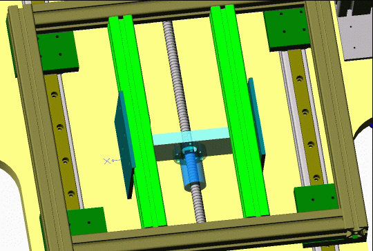
Below is a picture of the X axis. The X axis consists of a pair of linear rails mounted on a pair of aluminum extrusions.
Mounted to the rails are four ball bearing runner blocks . A frame of aluminum extrusions is mounted to the runner blocks and make up the moving table.
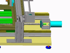
In the center is a lead screw with an anti backlash nut, At the far end is a motor mount and a stepper motor. When the stepper motors turns, the table moves back and forth on the linear rails.
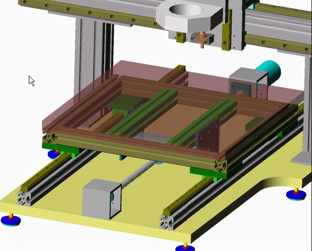
A motor mount is attached to the table at the far end. On one end a stepper motor is attached and the opposite end has a bearing block that contains two sets of bearings. The turned end of the lead screw rides on the inside of the bearings.
Not shown is a flexible coupler which is attached to the shaft of the stepper motor and the end of the lead screw.
The other end of the lead screw is attached to another square extrusion with a bearing block. The end of the lead screw is threaded. During assembly, a nut is placed on the thread and tightened (pre loaded) to the point that it remove any play on the lead screw.
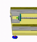
Mounted on the lead screw is an anti backlash nut. The nut is attached to the carriage assembly that makes up the moving table assembly.
Below is a picture of the Y axis. The Y axis is constructed similar to the X axis, and is mounted on the back of the Bridge (aluminum extrusion). The Y axis moves back and forth and at the same time moves the Z axis assembly.
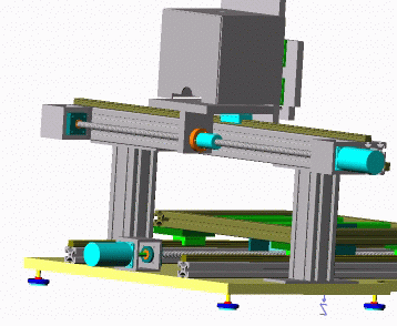
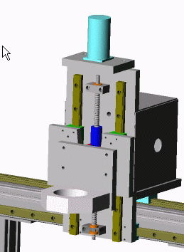
The Z axis assembly consists of a pair of rails and four bearings. Attached to the bearings is a flat plate. Between the rails is a lead screw and anti backlash nut.
One end of the lead screw is attached to the shaft on the stepper motor through a flexible coupler.
The front plate moves up and down powered by the stepper motor.
Attached to the front plate is another plate that has a router bracket attached.
Router plan will be aded- soon.
Related Posts
Basic Power Supply Design Pinout an Signals Serial cable connection Serial port monitor cable DNC Software Verify Code
Tuesday, January 03, 2006
RS232-Serial port
Intro to serial (RS232) port interface
The serial port is an I/O (Input/Output) device. An I/O device is just a way to get data into and out of a computer. There are many types of I/O devices such as serial ports, parallel ports, disk drive controllers, ethernet boards, universal serial buses, etc. Most PC's have one or two serial ports. Each has a 9-pin connector (sometimes 25-pin) (pic.1) on the back of the computer. Computer programs can send data (bytes) to the transmit pin (output) and receive bytes from the receive pin (input). The other pins are for control purposes and ground.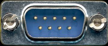
The serial port is much more than just a connector. It converts the data from parallel to serial and changes the electrical representation of the data. Inside the computer, data bits flow in parallel (using many wires at the same time). Serial flow is a stream of bits over a single wire (such as on the transmit or receive pin of the serial connector). For the serial port to create such a flow, it must convert data from parallel (inside the computer) to serial on the transmit pin (and conversely).
Most of the electronics of the serial port is found in a computer chip (or a part of a chip) known as a UART.
Pins and Wires
Old PC's used 25 pin connectors but only about 9 pins were actually used so today most connectors are only 9-pin. Each of the 9 pins usually connects to a wire. Besides the two wires used for transmitting and receiving data, another pin (wire) is signal ground. The voltage on any wire is measured with respect to this ground. Thus the minimum number of wires to use for 2-way transmission of data is 3. Except that it has been known to work with no signal ground wire but with degraded performance and sometimes with errors.
There are still more wires which are for control purposes (signalling) only and not for sending bytes. All of these signals could have been shared on a single wire, but instead, there is a separate dedicated wire for every type of signal. Some (or all) of these control wires are called "modem control lines". Modem control wires are either in the asserted state (on) of +12 volts or in the negated state (off) of -12 volts. One of these wires is to signal the computer to stop sending bytes out the serial port cable. Conversely, another wire signals the device attached to the serial port to stop sending bytes to the computer. If the attached device is a modem, other wires may tell the modem to hang up the telephone line or tell the computer that a connection has been made or that the telephone line is ringing (someone is attempting to call in). See section Pinout and Signals for more details.
RS-232 or EIA-232, etc.
The serial port (not the USB) is usually a RS-232-C, EIA-232-D, or EIA-232-E. These three are almost the same thing. The original RS (Recommended Standard) prefix became EIA (Electronics Industries Association) and later EIA/TIA after EIA merged with TIA (Telecommunications Industries Association). The EIA-232 spec provides also for synchronous (sync) communication but the hardware to support sync is almost always missing on PC's. The RS designation is obsolete but is still widely used. EIA will be used in this howto. Some documents use the full EIA/TIA designation. For info on other (non-EIA-232) serial ports see the section Other Serial Devices (not async EIA-232)
3.5 Data Flow (Speeds)
Data (bytes representing letters, pictures, etc.) flows into and out of your serial port. Flow rates (such as 56k (56000) bits/sec) are (incorrectly) called "speed". But almost everyone says "speed" instead of "flow rate".
It's important to understand that the average speed is often less than the specified speed. Waits (or idle time) result in a lower average speed. These waits may include long waits of perhaps a second due to Flow Control. At the other extreme there may be very short waits (idle time) of several micro-seconds between bytes. If the device on the serial port (such as a modem) can't accept the full serial port speed, then the average speed must be reduced.
Flow Control
Flow control means the ability to slow down the flow of bytes in a wire. For serial ports this means the ability to stop and then restart the flow without any loss of bytes. Flow control is needed for modems to allow a jump in instantaneous flow rates.
Related Posts


