The First STEP
The biggest step in this direction has already been taken. It's STEP, the STandard for the Exchange of Product model data, a comprehensive ISO standard (ISO 10303) that describes how to represent and exchange digital product information. STEP replaces IGES as the means by which graphical information is shared among unlike computer systems around the world. The big difference is that STEP is designed so that virtually all essential information about a product, not just CAD files, can be passed back and forth among users.
The core of the standard is a library of engineering definitions that can be assembled into various "application protocols" customized for the product models needed by particular industries and activities. A common library covers geometry, topology, tolerances, relationships, attributes, assemblies, configuration and other characteristics. New product models can be added as the need arises.
An extension to STEP has been created to cover product information related to CNC machining. This is STEP NC. STEP NC forms the basis for the scenario that caught your attention at the beginning of this article. The development effort to make STEP NC product model data usable as direct machine tool input has already progressed substantially.
In May 2000, a prototype for the sets of data required to add machining information to the product model of a test part was demonstrated. A later phase of this project will develop the machine tool controller capable of accepting this "super model" as input. The current test part is a milled workpiece. Turning and grinding are on the horizon. The "super model" demonstrated in May used an emerging Internet language called XML to add information about machining strategy, tool path planning, and tool selection. XML makes the resulting database "Internet ready'—a key requirement for global e-manufacturing.
STEP Vs. IGES
To understand STEP NC and where it's headed, a look at STEP and its relationship to IGES is the place to begin. IGES was about exchanging data and only the data contained in graphics files. STEP is about sharing data, allowing parties to work together by communicating information interactively.
IGES had its start 20 years ago when designers and engineers were turning to computers to create product designs. Instead of drawing lines and segment of circles on paper to make graphic representations of what a product should look like, they started making those lines and arcs on a computer screen. The completed design could be saved as a digital file. Although creating the original design file might take longer than preparing the engineering drawing on paper, the design file could be quickly copied, modified, printed and otherwise manipulated. These time savings more than made up for the extra time it took to prepare. Moreover, the digital nature of the design file allowed it to contain much more information in a much more flexible format.
One big problem quickly emerged. The computer-aided design (CAD) systems used to create these digital design files were not compatible with each other. A design created on a Computervision system was meaningless to an Applicon system, for example. Companies with unlike CAD systems could not exchange CAD data.
The effort to resolve this situation got underway in the spring of 1980. Representatives of U.S. user groups, vendors and standards organizations began meeting regularly to create a neutral, non-proprietary database structure and data format for CAD files, dubbed the Initial Graphics Exchange Specification (IGES). In theory, CAD files translated into IGES could be exchanged with any CAD system that could translate IGES files into its own proprietary format.
Although IGES eventually became a workable, if imperfect, approach to exchanging CAD files, a major shortcoming with this approach became apparent right away. IGES allowed one system to communicate the lines and symbols of a computerized engineering drawing, but IGES failed to communicate the meaning of the information the drawing was intended to convey. It did not provide a reliable means by which product features could be transmitted with the geometry so that computer-based applications could "understand" the engineering drawing.
While IGES was being developed and gradually made more functional as it moved through the standards formation process, efforts to develop a true "product data exchange specification" were launched. The goal of this effort was to capture and convey "logical" information about product features and provide "physical" mechanisms for data exchange. Originally conceived as a U.S. initiative, this effort was soon seen as requiring international participation.
By 1984, this international effort to develop a Product Data Exchange Specification had been established under the auspices of ISO, the international standards making body. The goal was to define the methods for creating product data models that could be interpreted by computers. These models were intended to allow the exchange and sharing of product data in a way that the meaning of the data would not change throughout the product life cycle.
The international standards covering these product data models became known as STEP. For the last 15 years, various groups and committees (mostly comprising users rather than vendors) have been meeting regularly to develop standards for product data models. They have made considerable progress. Because the STEP standards are now sufficiently developed to cover all of the original purposes of IGES, IGES will receive no further development and refinement. STEP has officially taken its place.
By July 2000, every major and almost all minor CAD system vendors had STEP translators in the latest releases of their CAD products. Moreover, these translators have been tested for conformance and interoperability. With only a few exceptions did any of the translators fail to operate effectively. (Indeed, one of the innovative features of the STEP formation process was the early commitment to include testing procedures for assuring that STEP-compliant systems would truly function as intended. This provision may have slowed development but it appears to have paid off in the end.) In short, STEP is working. According to industry analysts, more than one million STEP enabled CAD stations are in place around the world.
Tuesday, November 29, 2005
Part 2-3 - STEP NC-The End Of G-Codes
Thursday, November 24, 2005
Part 1/3 - STEP NC-The End Of G-Codes?
Imagine this: You call up a Web browser on the PC-based CNC at your machine tool. You go to a certain Web site. From a menu on the home page, you select one of the databases it accesses. A 3D image of a workpiece comes up. You click on an icon in the task bar and check a few parameters and default settings on a pop-up window. Then it's a click on the CYCLE START button. The spindle motor starts to whir, axes begin to move, coolant spurts out and chips are soon bouncing off the Lexan panels in the machine guarding.
According to efforts underway right now, it won't be long—a couple of years at most—before this scenario depicts how most shops will be running their machine tools. NC part programs as we've known them for almost 50 years will become passe. All that the machine tool controller will need is the digital product model represented by the 3D image on the Web page.
The CNC won't use G-codes. Everything it has to know about how to move the cutting tool is in the product model's database. There will be no need for creating a new and separate file of tool path data. Tool paths will be figured out in the CNC itself, based on the product model. That means there's no need for post processors either. Data will be formatted for execution by the machine within the CNC. And because the product model won't change, it will be available for machining "hard copies" whenever and wherever needed.
"Whenever" means as long as the product's life cycle is on-going. Twenty-five years is a typical life span for aerospace parts, for example. Neither changes in computer technology nor advances in machine tool technology over the years would affect the usability of the product model as machine tool input.
"Wherever" means anywhere an adequately equipped shop has authorized access to the product model database. With the Internet, that access is worldwide. Parts could be machined anywhere in the world through a global supply chain, with the digital product model serving as the universal "NC part program."
What will it take to make this dream come true? How much more has to be done to get there? How close are we right now?
Thursday, November 17, 2005
LENS Medical & Specialty
Optomec’s LENS systems are an ideal solution for a broad range of  high-performance manufacturing needs because they can fabricate superior metal components in less time and at a lower cost than competing methods.
Medical Device Fabrication
Medical device manufacturing is a regulated industry in which specialty metals are used extensively for the production of high-performance components. With its costs and time advantages, LENS is an ideal solution for applications including the development, prototyping and production of specialty surgical instruments and orthopedic implants, such as hip, knee and spinal devices. LENS can further be used to manufacture medical devices with a range of functional enhancements that improve wear characteristics and ultimate quality of life for the patient, such as:
- Quick turnaround for emergency procedures
- Longer part life and increased wear resistance reduces need for revision surgeries
- Lower weight and custom fit devices improve patient comfort
- Surface Texturing for improved integration with native tissue
Hybrid Manufacturing
The LENS system integrates well with conventional processes to create unique hybrid manufacturing solutions. For instance, LENS can be used to enhance an existing component by adding layers of wear-resistant material or other surface treatments. LENS can also produce value-added features on existing parts, such as adding a boss, mounting lug, or flange to a large cast component.
Advanced Product Development and Functional Prototyping
A LENS system serves as a powerful product development tool that facilitates basic materials research, design feasibility studies and functional prototyping. LENS offers unique flexibility in the geometries and material range it supports, enabling the use of innovative design concepts such as hollow and internal structures, and functional material gradients that incorporate mechanical property transitions within a single part.

Once a geometry and material or material combination has been identified, LENS can rapidly produce a 3-dimensional prototype with excellent mechanical properties that not only give the designer a view of form and fit, but also enable full functional and structural analysis. The tool-less process is driven directly from CAD data, so a prototype of a new design or a design iteration can be produced in a matter of hours, providing significant time compression advantages.
Tuesday, November 15, 2005
LENS Aerospace & Defense
Component Repair
Optomec’s LENS systems provide a production ready repair platform that delivers economic and functional benefits in terms of: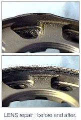
- Lower per-part repair costs
- Ability to repair heat sensitive components
- Reduced inventory requirements
- Longer service life
- Quick turnaround for rapid return to service
Key to its benefits, LENS is a highly targeted metal deposition technology that produces a very fine weld bead, exposing the component to far less heat than conventional methods. The resulting “heat affected zone” with LENS is smaller and more controlled so that the repair process does not damage the underlying part. And, since a LENS deposit is much finer and more precise than welding techniques, far less finishing work is required. Finally, with exceptional material and interface characteristics that are often superior to those of the native material, a LENS repair can potentially reduce future maintenance requirements.
Component Fabrication
High performance components are often made from specialty materials like titanium that are time consuming and expensive to produce using subtractive methods.
 In extreme cases, the Aerospace industry quotes “buy-to-fly” ratios for machined parts that can be as high as 15:1, highlighting the inefficiency and waste that is inherent in traditional methods.
LENS is an ideal alternative for producing such components because additive manufacturing provides for lower processing costs, faster turnaround, and significantly reduced material waste. The superior material properties with LENS serve to extend component life, reducing life cycle costs. The process also improves design flexibility by allowing novel geometries, structures and material gradients.
In addition to its ability to produce a complete part, LENS integrates well with other processes to create unique hybrid manufacturing solutions by adding high-resolution features to large forged or cast components, or by adding layers of wear-resistant materials as a protective surface.
US Army – Anniston Army Depot, Anniston, Alabama
The US Military’s maintenance operations alone support more than 500 ships, 16,000 aircraft, 50,000 ground vehicles, and other military assets at a cost of greater than $40 billion annually. The military repair applications for LENS cover aircraft, as well as land and sea based systems. In one example, the US Army’s Anniston Army Depot (ANAD) has been using its LENS system to repair a number of Honeywell gas turbine engine components for the M1 Abrams Tank. The Tank-Automotive & Armament Command (TACOM) has approved the LENS process, and ANAD estimates annual savings of up to $5 million using LENS to repair just a handful of approved components. With the success of this first system installation, ANAD has recently ordered its second LENS machine.
The US Army has also selected LENS for its Mobile Parts Hospital, which will provide a real-time battlefield repair capability that reduces the need to deploy large spare parts inventories and helps minimize down time of mission critical assets. The US Navy is implementing its first LENS system at the Naval Undersea Warfare Center (NUWC).
Sunday, November 13, 2005
Optomec LENS Technology
 Optomec’s LENS - Laser Engineered Net Shaping solutions have evolved from technology that was pioneered at the U.S. Department of Energy’s Sandia National Laboratories under the direction of Dave Keicher who now serves as Optomec's CTO and Vice President of R&D.
LENS utilizes a high-power laser (500W to 4kW) to fuse powdered metals into fully dense 3-dimensional structures. The LENS system uses the geometric information contained in a Computer-Aided Design (CAD) solid model to automatically drive the LENS process as it builds up a component layer by layer. Additional software and closed-loop process controls ensure the geometric and mechanical integrity of the completed part.
With an Optomec LENS system, the process is housed in a hermetic chamber which is purged with argon so that the oxygen and moisture levels stay below 10 parts per million. This helps to keep the part clean and prevents contamination from oxygen or nitrogen. The metal powder feedstock is delivered to the deposition head by Optomec’s proprietary powder-feed system, which is able to precisely regulate mass flow. Once a single layer has been deposited, the deposition head moves on to the next layer. By building up the successive layers, the whole part is constructed. When complete, the component is removed and can be heat-treated, Hot-Isostatic-Pressed, machined, or finished in any customary manner.
Optomec holds numerous patents and has many patents pending on its proprietary LENS process and equipment.
Development History
The process underlying LENS is a mature technology kernel that has been under development for more than twenty years. Since 1997, Optomec has focused on making substantial investments in proprietary process, system and control enhancements in order to provide a robust solution that can meet the demanding requirements of industry. Likewise, Optomec has worked extensively with the US Department of Defense (DoD) and major aerospace, defense and medical device OEMs to ensure that commercial LENS systems address the production needs of our users.
Metallurgy Briefing
The LENS system can process a wide variety of metals including titanium, nickel-based super alloys, stainless steels, tool steels, etc. – all of which are commercially available in the requisite powder form. The results from LENS consistently demonstrate better metallurgical and mechanical properties than other processes due to an improved microstructure with significantly reduced grain sizes. For example, LENS-deposited 316SS typically has a cellular spacing of just a few microns, which leads to yield strengths approaching twice that of conventionally processed 316SS.
Friday, November 11, 2005
3D scanning made easy
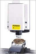
One of Datron's latest products is set to make the copying of 3D objects cheaper and easier than ever before. The Copymate, by Israeli company Graphitech, is a scanner that simply plugs into any machine. The resulting computerised model can be edited before being machined into a finished item.Graphitech's objectives in developing the Copymate were ease of use and affordability. Installation is simple, and the user is guided by a wizard through the process of scanning, creating a machine tool path and sending the job to the milling machine. A by-product of this user-friendly approach is low operating costs to match its competitive price.The scanning itself is extremely rapid. An 8"x9"x3" object, for instance, can be scanned in 27 minutes, to an accuracy of 0.008 inches. Surface generation takes just 53 seconds, while the toolpath can be generated in four and a half minutes.If manipulation of the image before milling is required, the Copymate is complemented by Graphitech's Cimagrafi software. This art-based CadCam system is highly regarded in the industry, as it is intuitive, easy to use and built in a modular fashion, so it can be tuned to an individual customer's exact requirements. It has been a significant force in the market for the last five years. The release of Version 7, the next development, is hotly anticipated during this year.
Thursday, November 10, 2005
Goelan-innovative Cam software
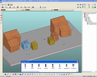
Thanks to a new innovative, rapid and efficient method (based on the group's 30-year experience), the pure CAM software GOelan allows any company using digitally controlled machine tools to program them for unprecedented productivity.
GOelan is interoperable with the main CAD software packages (including TopSolid, but also numerous other CAD systems) and enables fast, simple and powerful programming for the manufacture of parts that are perfectly defined by a design or a sequence of NC commands.
Key features of GOelan
- Revolutionary, entirely redesigned interface
- Rapid familiarization - intuitive and comfortable to use
- Time savings times three
- Permanent management of modifications and errors
- Training made easy by 6 training wizards that can be called at any time
- Automatic re-calculation of blocks whenever a tool or machine is changed
- Selection of the tools definition order, schedules and areas to be machined
- Permanent control of the raw part or of the distance between 2 segments with a single tool
- Multiple viewing options that are easily identifiable and close to hand
- Wealth of industry-specific functions closely associated with your methods
- Integrated 2D and 3D programming
Other group products integrating CAD, CAM, and CAPM
In the manufacturing market, the strength of CAD/CAM suppliers lies in their ability to simultaneously provide design technologies and manufacturing technologies and to link them in a simple and yet coherent process. This must be supplemented by Engineering Data Management and computer-aided production management (EDM and CAPM). The strength of Missler Software is that, historically, it has thorough expertise in the twin fields of CAD and CAM. This competence is reinforced by a knowledge of CAPM systems for small and medium-sized enterprises, as used by more than 400 companies in France.
This gives rise to two perfectly compatible product lines, headed by Engineering Data Management and computer-aided production management:
TopSolid: This integrated mechanical CAD/CAM solution enables design and manufacturing data to be linked in a given environment for very diverse fields of mechanical engineering: machines, plastic parts, tooling, sheet metal work, general mechanical design, etc. TopSolid is designed for all manufacturers and subcontractors that need to do major design work related to manufacturing, and to simulate and control part production very precisely.
TopSolid/PDM and TopManufacturing: these solutions enable organization and management of all technical data and workflows implemented during the manufacturing and design processes.
Thursday, November 03, 2005
"CncPlayer", what is that actually?
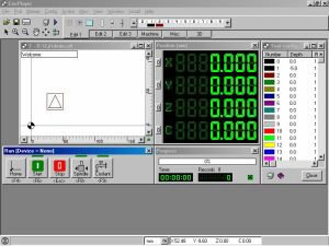
The CncPlayer is a software that plays your cnc files, hence CncPlayer or CP for short and controls your stepper motor driven cnc machine accordingly.
Even the CncPlayer is under construction, certain functions like cutter radius compensation, tool path optimization, DXF to HPGL (*.plt) conversion, milling simulation and more are already in an useful shape.


