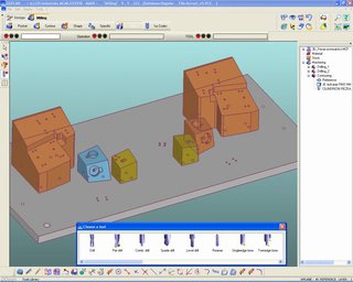
Delcam will demonstrate the Simpleware ScanIP software for producing STL files using data from MRI and CT scanners for the first time at the Medical Device Technology exhibition to be held at the NEC, Birmingham, on 15 th and 16 th February. The company recently signed an agreement with Simpleware to sell ScanIP through its international reseller network.
ScanIP allows segmented image data from MRI and CT scanners, and similar equipment, to be converted into STL files or, with the addition of the +ScanFE module, into meshed volumetric models suitable for FE and CFD programs.
MRI and CT scanners are used principally in the medical and dental industries and the addition of the Simpleware programs to Delcam’s Power Solution range of product development software will help the company to provide broader and better-integrated solutions to those sectors.
STL files generated from Simpleware’s ScanIP software can be read into Delcam’s CopyCAD reverse engineering program or the company’s PowerMILL CAM system. CopyCAD includes a range of options for editing STL data, including sculpting and smoothing tools to produce higher quality models, methods for filling any holes in the data with tangent-matching surfaces, and the ability to combine the scanned results with prismatic surfaces or shapes.
CopyCAD also enables STL files to be converted into fully-surfaced CAD models. The software includes many powerful features, including the ability to combine multiple files into a single model, and the ability to generate internal surfaces by offsetting the external data.
Delcam’s PowerMILL CAM software has the ability to machine models from STL data. Its fast calculation speed and wide range of machining strategies make it ideal if a physical model needs to be created from the scan data. Such physical models can often be more helpful than computer images, for example, when planning or rehearsing complex surgical procedures.
Thursday, December 29, 2005
Delcam will demonstrate the Simpleware
Tuesday, December 27, 2005
New Version of C Series Press Brakes Introduced

Providing basic, introductory-level machines, C Series includes programmable back gauge, 4-cylinder ram drive, and Bendguard to ensure safe bending. Rated at 73 tons with 82 in. of bending length, Model C66 offers advance and reverse travel speeds to 472 ipm, and Y1/Y2 dual axis ram control with +0.0004 in. repeatability. It can be configured with 2- or 4-axis back gauge and comes standard with manual bed crowning.
more…
Friday, December 23, 2005
Wireless Chipset supports data rates to 240 Mbps
Based on single chip with 2 complete, fully integrated radios, True MIMO Gen3 Chipset enables content such as media-rich Internet, large files, video, IPTV, music, photos, and games to be distributed across wireless network without compromise in performance, while remaining 100% compatible with 802.11b, g, and Wi-Fi. Product provides actual TCP/IP throughput over 120 Mbps with compressed traffic, surpassing performance of wired 100BaseT Ethernet. more…
Long Ball Screws Deliver CNC Machine with Less Noise
FEATURING UNIQUE BALL CIRCULATION SYSTEM:
SKF® long lead ball screws feature a unique ball circulation system designed to promote high linear speeds and low noise levels. These ball screws are ideally suited to provide precise positioning in a wide range of linear-actuation applications, including packaging and automation systems, laser cutting, woodworking, and production machinery, among others.Long Lead ball screws are available with a nut with axial play (Series SL) or with backlash elimination (Series BL) to achieve the desired operation. 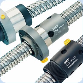 Smooth performance is enhanced with the optimized end cap ball recirculation system.The standard product range also includes a rotating nut design (Series SLT and BLT) for applications where critical speed or inertia is an issue. The SLT and BLT rotating nut option is a design that allows the drive motor to move with the nut, which results in reduced inertia, less required power, and even higher linear speeds up to 110m/min.Long lead ball screw diameters range from 25mm to 50mm and leads range from 20mm to 50mm.All SKF long lead ball screw assemblies can be equipped with the necessary end machining and with the support bearing package pre-assembled and ready to go. They can further be customized with double protection wipers and brush wipers in both cylindrical or flanged nuts configurations. Standardized long lead screws users can be customized to satisfy any particular application specifications.
Watch Video
Thursday, December 22, 2005
3DCS Technology Helps New Embraer 190 Airplane
3DCS is a World Class Tolerance Simulation Tool that allows you to model the effect of variation on an assembly, Determine the "Robustness" of your design, and test Alternative Tolerancing Schemes. 3DCS is a True 3D modeling system that visually depicts variation in your design, and statistically simulate production of your "Virtual Assemblies." But it doesn't require that you purchase an Expensive Workstation. more...
Wednesday, December 21, 2005
Plunge milling offer better productivity
Plunge milling along a pattern of arcs may offer an even better way for slower machines to mill pockets productively.
Plunge milling offers a way to mill deep pockets productively without the need for high speed machining. An older machining center may be slow, but as long as the machine is fairly rigid, it can potentially achieve a high metal removal rate by roughing out material in a series of overlapping plunges with a long tool. These plunges are straight Z-axis moves into the work, similar to drilling moves. Certain milling cutters are designed to be effective at cutting this way, and according to CAD/CAM developer Delcam, a certain pattern of plunges is also more effective for this kind of cutting.
Delcam explained its ideas about plunge milling as part of a conference related to aerospace machining that the company recently held in Paris, France. In plunge milling, the company says, few give thought to the tool path. Most users tend to assume that straight, parallel rows of plunges are sufficient.
This "raster" pattern of plunging proceeds as follows: After an initial hole is machined (perhaps by drilling), the first milling plunge overlaps with this hole. (Every plunge has to overlap with open space so that chips can escape.) The second plunge then overlaps with the first, and so on—in a straight row of plunges that runs the length of the pocket. After the first such row is done, the tool steps over to do a second row that overlaps with the first row, and so on.
That approach creates problems for the first row, Delcam says. The "slot" machined in this way leaves little clearance for chips to escape, so chip compaction is likely. Also, every plunge along this row overlaps with nothing but the preceding plunge, so material engagement tends to be high.
Another problem is that a series of straight rows may not be a good fit for the shape of the pocket. This is particularly true of the many odd-shaped pockets typical of aircraft parts. If the pattern of plunges can’t conform to the pocket’s shape, then "upstands" of remaining material may be left around the pocket’s edge.
The company says a better approach is to let sequential plunges follow a pattern of circular arcs. An initial hole is still the starting point, and the first plunge overlaps with this. But then, the second plunge may overlap with both the first plunge and the initial hole, and so on—with the plunge following an arc that orbits around the initial hole. The second series of plunges then may follow a larger arc that orbits around this plunged-out area, and so on.
One clear advantage of the typical, straight-line pattern of plunging is ease of programming. Straight rows of plunges are easier for the software to generate. A more complex pattern such as an array of arcs has to be drawn by the programmer. The machining cycle following this pattern does have the potential to be both more productive and more effective, the company says, but programming does take a bit more time.
Tuesday, December 20, 2005
3Dconnexion SpacePilot 3D Motion Controller
Created to dramatically boost productivity, the new device couples 3D motion control with an array of function keys powered by adaptive technology.
SpacePilot incorporates a built-in LCD display that allows users to view dynamically labeled and extendable key assignments. The SpacePilot can be used with CAD and other 3D modeling software but also adapts to Microsoft Office.
More details in 3Dconnexion press-release.
Friday, December 16, 2005
New Solutions for the Die and Mold Industry
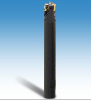
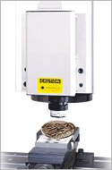
In many situations in the die and mold industry, there is a need to machine deeper than the length capabilties of the standard endmill range. With the long HELI2000 cutters the tools may be used in a collet chuck and set to the length required by postioning in the chuck, or in the case of Weldon shank the cutter can be cut to size to suit the operation.
Why Reduced Shank Diameter?
Many applications require machining along a high vertical wall or pocket.
By reducing the shank diameter by one millimeter, a clearance is created between the machined wall and the tool shank. This has major advantages for the user where interference of the tool shank and the machined surface may occur.
Two Endmill Options:
- Long Shank
- Reduced Shank Diameter
- The HM90 range of endmills (HELI2000) is now available in longer lengths for the die and mold industry and also with reduced shank diameter for machining deep vertical walls.
Tool Advantages:
- Increased life of the tool body.
- High 90o shoulder accuracy.
- Large choice of chipformers is available using HELIMILL inserts
- APKT 1003 and ADKT1505 inserts may be mounted on these HELI2000 cutters.Long reach for deep cavities
- Length can be set by user
- No interference of the tool shank with the side wall of the workpiece
- High accuracy of HELI2000 designUtilizes the improved cutter body life of HELI2000
- Tool are available in a diameter range of 16 to 40 mm (.38 to 1.50")
in a variety of configurations
Friday, December 09, 2005
Sodick wins major Japanese design award
Sodick’s ground-breaking Premium range received further praise recently when the AQ327L was announced as a winner of the esteemed “Good Design Award” for product design in the machine tool industry field. This prestigious accolade, awarded by the Japan Industrial Design Promotion Organization (JIDPO), recognises excellence in the field of innovation and technology and is judged on a broad spectrum of criteria such as making skilful use of new technology and meeting the needs of consumers. A winning design must also convey versatility and a high degree of functionality in an easily understandable way, offer a high level of performance and be user-friendly. Most importantly it should be good value for money and have a long useful life.The AQ327L Premium design is based on specific core technology which is the cornerstone of all Sodick machines; linear motors, ceramic components, sturdy Meehanite castings and Sodick Motion Control. These factors combine to ensure a long life, low maintenance, durability and performance. The addition of a high speed generator, vertical drop tank and Super Pika W fine finishing circuit have put Sodick Premium machines at the forefront of EDM manufacturing.Sodick will showcase the award winning Premium machines in Hall 8, Stand P42/O43 of Euromold 2005, together with other EDM machines from the high-technology, high-performance wire, sink and milling ranges. The show runs from 30th November to 3rd December at the Exhibition Centre, Frankfurt/Main.
Wednesday, December 07, 2005
More than needs - Ati's FireGL V5000
The FireGL V5000's PCI Express interface should appeal to system integrators, OEMs and medium-sized companies alike. Performance wise, it is hot on the heels of its bigger brother, the V5100, and is thus geared for the mid-tier market.
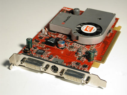
Designing engineers that don't always work on highly complex models will find this card a solid choice. It even offers a little added value, namely support for DualLink. Thanks to this feature, the card can be connected to nine-megapixel digital flat screens. As a comparison, the V5100, V3200 and V3100 cards only come with Single-Link functionality, but at least dual-monitor operation is standard throughout the FireGL line.
The recommended retail price of $699 ($630) should soon be undercut by online retailers. Customers ordering in bulk should also be able to expect discount prices, as the V5000 is very cost-effective to produce, thanks to its 110-nanometer manufacturing process. The list of design-win partners include Alienware, ABS, Boxx, Colfax, Elsa, Matek, Maxdata, Monarch, Research Machines, Sys Tech, Xi Computer and Xworks Interactive.

ATI’s FireGL Provides Graphics Horsepower...
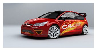
Success in the competitive automotive market requires the production of innovative vehicles that meet critical design requirements in performance, handling, aerodynamics, comfort and safety. Accomplishing this requires highly skilled engineers and designers, industry expertise and advanced technology.

Paris-based PSA Peugeot Citroën recognizes the importance of technology to its success. The European automotive icon is currently pursuing a product development plan that will see it launch 26 vehicle models worldwide between 2003 and 2006. Workstation systems featuring high performance FireGL graphics accelerators are essential to meeting their development goals.
ATI FireGL Plays a Crucial Role
PSA Peugeot Citroën is Europe’s second-largest automotive manufacturer, employing more than 207,000 people around the world and selling more than three million vehicles per year. The company recently opened a new state-of-the-art complex near Paris dubbed the Automotive Design Network (ADN), a 70,000-square-meter facility dedicated to design innovation.
ATI’s FireGL workstation graphics accelerators are one of the key components in the Unix workstations at the new ADN complex and other PSA Peugeot Citroën sites in France, Europe and around the globe, including Argentina, Brazil and China. Currently, the automaker utilizes 3,000 HP C8000 workstations powered by FireGL accelerators.
"We ultimately selected FireGL accelerators for the unmatched performance and flexibility they provide us in the Unix world," states Alain Gonzalez, IT Architect for PSA Peugeot Citroën. "It’s also important to note that, together with HP, ATI is the first and only manufacturer to offer the AGP graphics support for Unix that we require.
A History of Success with ATI
PSA Peugeot Citroën began using FireGL accelerators in 2001, so the move to ATI’s latest Unix product is a natural progression in an ongoing strategy to advance the car maker’s design and manufacturing capabilities and processes, according to Gonzalez.
"Our designers face a constant need for onscreen 3D imaging and rendering that is extremely fast, precise and reliable.  The FireGL graphics accelerator in their C8000 workstation delivers unmatched performance and features, streamlining the design process and allowing them to complete their work in less time."
Precise and accurate 3D renderings are not only crucial to engineers for visualizing and developing designs, but also for simulating how individual components will fit, interact and perform together under real world driving conditions. The ability to manipulate complex images and huge files easily onscreen during simulations is a key requirement.
"It’s essential that our designers’ Unix workstations deliver 3D visualization that streamlines the process of getting our cars from concept to completion," says Gonzalez. "With FireGL technology, we know we are going get the best image quality, 3D features and overall performance for the job."
Putting the Virtual Car on the Road
"ATI graphics cards let us build the virtual car in ways that anticipate the relationship of various complex components and test the durability of our designs," says Gonzalez. "Designers can modify large assemblies quickly and easily, and create precise visual renderings. Time is of the essence and ATI keeps workflow moving smoothly."
While PSA Peugeot Citroën is bringing new vehicles to market at an ever increasing pace, it keeps a close eye on meeting cost and quality targets, two fundamental concerns for the organization.
The company’s IT department routinely surveys engineers for feedback on design tools like the HP workstations with FireGL. "The objective is to understand the day-to-day challenges facing the engineering team in order to address their design needs for the future," Gonzalez continues.
"We have been able to reach a new level of performance that allows us to solve design problems and complete projects quickly and reliably thanks to ATI Technologies," Gonzalez says. "Any problem is ‘solvable’ if you’re willing to spend what it takes to solve it. However, ATI allows us to maintain a balance between low costs and exceptional graphics performance. The price performance value they offer is unsurpassed."
Gonzalez also appreciates the ATI workstation group for their expertise and dedicated support. "Another significant factor for us is that ATI is a partner willing to listening to our needs. ATI understands our requirements and provides us with the tools and capabilities necessary for us to produce world class vehicles. There is no question that we have a competitive advantage thanks to ATI."
Tuesday, December 06, 2005
CATIA - Imagine & Shape 2
Dedicated to aesthetical shapes creation for industrial and conceptual design, CATIA - Imagine & Shape 2 (IMA) introduces very new concepts, breaking the traditional approach of surfaces modeling. It could be used in any domains needing quick surface creation, including rapid virtual prototyping, ideas expression and simulations. CATIA - Imagine & Shape 2 (IMA) combines a powerful technology, based on subdivision surfaces, and a simple use, making easy for a non surface specialist to design within a CAD system. CATIA - Imagine & Shape 2 (IMA) is really shaped to leverage in V5 the engineering of emotional content: From ideas to 3D becomes then quick and easy for all.

Expert-Technology Not Always Best Holiday Gifts
Beverly J. Davis, an associate professor of organizational leadership and supervision, says the holidays are a prime time to be wary of falling victim to what she calls "technoism," and blindly purchasing each new technology.
Davis defines technoism, a term she coined, as the tendency to impulsively purchase or use new technological devices out of a fear of being labeled old-fashioned instead of based on need. This time of year, technoism can run rampant as companies unveil new products for the holiday season and young people clamor for the latest, trendiest gadgets.
"Each year electronics companies come out with new versions of their products for the holiday season," Davis says. "Ask yourself, is this newest video game system or MP3 player worth the several hundred dollars to upgrade from what you or your children already have? Or, are you just buying it so that you can have the newest, flashiest products? At this time of year, kids are very good at reflecting technoism onto their parents by pressuring them to keep them in the technological loop."
Davis says people should evaluate the gifts they buy in the same way they evaluate technology purchases they make for themselves. Avoid technoism by considering whether the technology you are buying will be used and whether it will actually make life easier or better, she says. Avoid making purchases simply because something is new or because you want to keep up with friends who may be purchasing the gadgets.
Monday, December 05, 2005
VISI-Series - machining STRATEGIST
The Shop Floor Machining Solution machining STRATEGIST is a CAM system designed for high speed machining with built-in logic for use with solid carbide and carbide insert cutters. Developed by the people at Vero International in England, machining STRATEGIST is used in Mold, Tool and Die, Prototype and Pattern shops for generating cutter paths on complex geometry developed in disparate CAD systems such as VISI-Modeling, CATIA, Unigraphics, Pro/Engineer, SolidWorks, and Solid EDGE.
Most popular CAM systems that are used in today's mold shops weren't designed with High Speed Machining in mind. In order to take advantage of today's cutter and machine tool technology, machining STRATEGIST had to be and was designed completely from scratch. Released less than 6 years ago, it is the newest technology on the market today.
Using the latest software development tools, Vero people created a CAM system that generates efficient toolpaths very quickly, while still maintaining unparalleled ease of use. Strategist also takes advantage of multiple processors for more productive programming. But, the biggest advantage of machining STRATEGIST is in it's toolpath generation. Because it maintains a cut stock boundary, it knows exactly where to go to remove stock. It allows use of higher feedrates because toolpaths are created without any sharp corners so cutter deflection is maintained more constant. And all this allows your CNC machines to run faster and more productively with less wear and tear.
Advanced Rest Machining
Steep and shallow areas are machined in a single toolpath with different strategies - steep and shallow machining - for each. Crucially, rest machining can be calculated in areas where the final cutter is smaller than the curvature of the part.
Point ReductionAll machining passes operations now support enhanced point reduction and arc fitting. Arc fitting is enabled by default for those operations where it is likely to have the biggest benefit. In benchmarking, reductions of over 50% in NC file size have been observed.
Horizontal Finish Machining
Horizontal surface machining has been designed to use a flat-based cutter. This strategy will dramatically reduce the time it takes to finish machine the flat areas on a complex 3D mould, and in finish machining pockets in aerospace components.
Rest Roughing
The system will calculate the rest areas of a selected toolpath - areas left on the surface that have been insufficiently machined - generate a stockmodel with this information, and edit passes to it.
This is a good way to generate efficient toolpaths, reducing air-cutting and shortening the machining time.
Morph Machining
Each pass in a morphed "patch" - the toolpath prior to linking - echoes the shape of the one before, while suggesting the shape of the one after. Akin to machining with the flow of a surface but by creating a set of boundaries with control points, the operator can exercise tight control on how a toolpath flows as it is mapped onto the model.
It is now possible to access two advanced machining presets quickly and easily from the menu, consolidating pencil milling and constant surface stepover.
Parallel Pencil Milling PassesA set number of passes are offset from an active boundary or existing single line toolpath.
Tapered cutter support extends to carbide insert button cutters, predominantly used for roughing. To leave a tapered finish, it is critical to rough with taper to leave a material-on condition.
Part 3-3 - STEP NC-The End Of G-Codes
STEP NC
Although STEP NC has not quite completed the formal standards making process, it is well into the review and approval cycle, which will ultimately settle a few remaining matters of technical detail. STEP NC defines data representing "working steps," that is, a library of specific operations that might be performed on a CNC machine tool. In keeping with the STEP concept, these working steps are generic descriptions that can be incorporated into a product model. These descriptions are not linked to a specific format or code. However, STEP NC working steps are roughly equivalent to the machining commands represented by traditional M and G codes.
STEP NC is the basis, the enabling standard that underlies the potential for using the digital product model as machine tool input. STEP NC allows a complete database of machining information to be built around it. The database, then, dictates what capabilities must exist in the machine tool controller to cut the part.
What's called for is a "super model" that includes design information such as geometry, manufacturing planning information such as form features (holes, slots, contours and so on), plus manufacturing strategy information such as tool selection, fixture location and so on.
The effort to develop the super model and make it usable as machine tool input is being spearheaded by STEP Tools, Inc. of Troy, New York. STEP Tools is a developer of data exchange software for worldwide manufacturing. Although the official name of the project is the Model Driven Intelligent Control of Manufacturing, participants are simply calling it the Super Model project. Funding is coming from the National Institute of Standards and Technology (NIST), an agency of the U.S. Commerce Department's Technology Administration. The Super Model program was formally launched as an Advanced Technology Project with an award of $2.9 million in October 1999. Participating in the program is an Industrial Review Board consisting of manufacturers, software vendors and machine control builders, government and defense agencies, and a range of small- and medium-sized job shops from the Hudson Valley in New York State.
The Super Model project has a three year time line. The target for the first year is to build a STEP and STEP NC database containing three kinds of manufacturing features, and use the database to drive a machine tool controller. The target for the second year is to build a database containing all of the features defined by the STEP NC milling schema and use that database to manufacture the STEP NC test part. The target for the third year is to produce a database for another machining process such as turning, grinding or electrical discharge machining.
The Super Model Database
The challenge for the Super Model project is to create interfaces that bring together the information defined by STEP and STEP NC. Product geometry can be defined by one STEP application protocol. Product features can be defined by another STEP protocol. Machining operations can be defined by STEP NC. However, all three types of data and others must be integrated in a complete product model database. Moreover, this database must be Internet compatible.
Starting with product geometry in the STEP format is the easy part because STEP translators are built into most CAD systems these days (and they handle 3D geometry, doing so more effectively than IGES ever did, apparently). The super model test part happened to be created in a ProEngineering workstation.
The next step in building the database is adding features to the geometry. For the sake of demonstration, STEP Tools originally used a Microsoft Excel spreadsheet to link STEP-defined feature names to the test part geometry. The Super Model program is evaluating an automatic feature recognition system being developed by Honeywell FM & T, one of the subcontractors in the program. Called the FBMach Process Planning System (FBMach is short for feature-based machining), this software reads STEP geometry and automatically determines what features, such as holes, pockets, slots, and so on, are represented by the geometry. The user interface allows these determinations to be validated before proceeding. The FBMach system is expected to be available commercially by the end of 2000. Its application to the super model test part will be demonstrated in November.
STEP NC establishes a hierarchy of workingstep supertypes/subtypes. In other words, it breaks down every machining operation into the steps required to perform the operation. These steps include actions to be taken as well as data (such coordinates of point-to-point motion) to be applied. These steps are then linked to the appropriate part model geometry to fill in the values. STEP Tools is setting up tables to match workingsteps, workingstep-methods, workingstep actions, and machined features.
According to Martin Hardwick, president of STEP Tools, the super model database is adapting a modified version of the company's ST Repository product data management software to structure the database. Each repository uses standard interfaces to import and export geometry, features and workingsteps to the tools used by CAD and CAM engineers.
A key part of STEP Tools approach to the super model database is the use of XML in its interfaces. XML, the eXtensible Markup Language, is a vendor-neutral data exchange language for passing information, not just data, across the Internet. XML allows data to be "tagged" so that software applications reading the database can identify what type of information is stored in the database and extract the data that is needed. HTML, the Hyper Text Markup Language, is a similar"metadata" language that the Web uses so that text can be displayed no matter what Internet browser happens to read it. XML offers a comparable level of interoperability. An XML standard for STEP is nearing completion. This standard will ensure that all data in a product model is "tagged" in the same way.
For the super model, XML provides a convenient means to link manufacturing strategy, tool pathing, and tool selection information to geometry, features and machining steps in the database. By sorting out data with the appropriate tags, for example, geometry identified as a hole to be drilled can be linked to operations such as rough drilling, boring and counterboring steps. Each of these steps will require that other data be extracted, such as workpiece material, surface finish requirements, and so on, to link with speed and feed tables. XML provides the tags so that the data is sorted correctly.
Ultimately, XML ensures that a CNC networked to the Internet will be able to find the information it needs from the product model database to machine a part.
At the May 2000 Industrial Review Board meeting, STEP Tools demonstrated how XML transactions had been used to complete a database for its test part, linking the required information for three different types of machined features, including a hole, a slot and a pocket.
Down To The CNC
The goal for the Super Model project is to show how these features can be cut on a machining center using the product model as the NC part program, so to speak. One of the subcontractors deeply involved is this phase of the program is Electro-Mechanical Integrators, Inc. (EMI) of Franconia, Pennsylvania. Engineers at EMI are writing new software for a Bridgeport control unit that will enable it to accept STEP NC data. (The company has considerable experience with Bridgeport control units and is the factory-authorized support and repair agency for the Bridgeport DX32 control.)
According to Bart Stater, head programmer of EMI, this effort requires a customized command parser and command interpolator to process STEP NC. "Essentially we are creating a new CNC protocol to interpret the information in the product model in real time. This software will extract the data it needs to determine axis moves, get the specified tool, and issue commands. It will not need or use G-codes," he says. Otherwise, the I/O structure and servo system of the machine remain the same. He notes that this concept assumes that the CNC will be networked to a file server that receives and stores data, most likely through an Internet connection.
EMI is looking at two approaches to configuration of the CNC. One approach runs all of the executive software in the CNC's internal processors. Another approach uses a "PC front end" interfaced to the CNC. The PC would process the STEP NC data and spoon feed it to the CNC, filling a buffer with blocks of data on demand. This approach would ensure that the CNC is not starved for data while the product model is processed.
In November 2000, EMI is scheduled to demonstrate actual cutting of the three selected workpiece features on the test part. Although the concept could be proven with a simulation of the machining operations, cutting chips is a more convincing demonstration. "We want to show the CNC accessing the product database on the Web, finding the features to be machined, then generating commands to drill the hole, mill the slot and machine the pocket," Mr. Stater insists.
STEP Tools is also working with the Lawrence Livermore National Laboratories, where a STEP NC interface is being developed for the OMAC (Open Modular Architecture Control) project. Additional shopfloor tests and demonstrations of STEP NC are set to take place at a production machining facility operated by General Dynamics Land Systems in Scranton, Pennsylvania. A pilot project at the Jet Propulsion Laboratory is also in the proposal phase awaiting funds.
Art To Part
Those three words sum up the promise of STEP NC and the Super Model project.
From a shop floor viewpoint, art to part means the intermediate steps of creating an NC program are eliminated. Most of those intermediate steps necessitated a transformation of product data, causing data files to proliferate. Part geometry had to be translated, reconstructed or edited. The edited, translated or reconstructed geometry had to be processed to generate tool paths. Tool path files had to be post processed to suit the requirements of the machine tool and control unit combination. Postprocessed files were often edited on the shop floor. In short, one piece of part geometry begot hundreds by the time the part was actually cut from metal.
With STEP and STEP NC, the digital product model database replaces all of the other product data files otherwise created to make the part.
From a design and engineering viewpoint, art to part means that design and manufacturing can be managed with a single database. Just as data files need not proliferate down the supply chain, they need not proliferate across the manufacturing organization. Product data can be shared between products, between corporate divisions and between applications. The Internet will make this sharing of data global and virtually instantaneous.
This concept of art to part does make G-code programming obsolete. But this traditional form of programming for machine tools was already on its way out. Advances in CAM software make G-codes less and less visible to programmers and machine operators.
This concept also implies that CAD and CAM will have a different relationship than they did in the past. Dr. Hardwick believes that product models will originate in CAD, with STEP enabling a high degree of collaboration between designers and engineers. Feature recognition will be applied at this level as manufacturing engineers define the manufacturing process that becomes part of the product model. "At this point, the process data will be ready for any machine tool but will allow for important local parameters to be defined when it gets to the machine," he predicts. Selecting cutting tool, setting feeds and speeds and so on will be handled at the machine tool on the shop floor.
These CAM functions become the domain of intelligent controllers with on-board CAM software. This software will generate the movements necessary to make the parts after the appropriate parameters have been set on the CNC. "The on-board CAM software is there to do the last minute custom tool path generation using selections made by the operator," Dr. Hardwick says. Intelligence built into the software stops the operator from making mistakes or using less than optimum settings. "It's a huge opportunity for the CAM industry. This software will be a required component of all future CNCs," Dr. Hardwick contends.
Vision
With the development of STEP NC, what's happening is not simply the re-shaping of CNC. It is the reshaping of manufacturing. And in the vision that is emerging, the CNC machine tool will be more important than ever.
Tuesday, November 29, 2005
Part 2-3 - STEP NC-The End Of G-Codes
The First STEP
The biggest step in this direction has already been taken. It's STEP, the STandard for the Exchange of Product model data, a comprehensive ISO standard (ISO 10303) that describes how to represent and exchange digital product information. STEP replaces IGES as the means by which graphical information is shared among unlike computer systems around the world. The big difference is that STEP is designed so that virtually all essential information about a product, not just CAD files, can be passed back and forth among users.
The core of the standard is a library of engineering definitions that can be assembled into various "application protocols" customized for the product models needed by particular industries and activities. A common library covers geometry, topology, tolerances, relationships, attributes, assemblies, configuration and other characteristics. New product models can be added as the need arises.
An extension to STEP has been created to cover product information related to CNC machining. This is STEP NC. STEP NC forms the basis for the scenario that caught your attention at the beginning of this article. The development effort to make STEP NC product model data usable as direct machine tool input has already progressed substantially.
In May 2000, a prototype for the sets of data required to add machining information to the product model of a test part was demonstrated. A later phase of this project will develop the machine tool controller capable of accepting this "super model" as input. The current test part is a milled workpiece. Turning and grinding are on the horizon. The "super model" demonstrated in May used an emerging Internet language called XML to add information about machining strategy, tool path planning, and tool selection. XML makes the resulting database "Internet ready'—a key requirement for global e-manufacturing.
STEP Vs. IGES
To understand STEP NC and where it's headed, a look at STEP and its relationship to IGES is the place to begin. IGES was about exchanging data and only the data contained in graphics files. STEP is about sharing data, allowing parties to work together by communicating information interactively.
IGES had its start 20 years ago when designers and engineers were turning to computers to create product designs. Instead of drawing lines and segment of circles on paper to make graphic representations of what a product should look like, they started making those lines and arcs on a computer screen. The completed design could be saved as a digital file. Although creating the original design file might take longer than preparing the engineering drawing on paper, the design file could be quickly copied, modified, printed and otherwise manipulated. These time savings more than made up for the extra time it took to prepare. Moreover, the digital nature of the design file allowed it to contain much more information in a much more flexible format.
One big problem quickly emerged. The computer-aided design (CAD) systems used to create these digital design files were not compatible with each other. A design created on a Computervision system was meaningless to an Applicon system, for example. Companies with unlike CAD systems could not exchange CAD data.
The effort to resolve this situation got underway in the spring of 1980. Representatives of U.S. user groups, vendors and standards organizations began meeting regularly to create a neutral, non-proprietary database structure and data format for CAD files, dubbed the Initial Graphics Exchange Specification (IGES). In theory, CAD files translated into IGES could be exchanged with any CAD system that could translate IGES files into its own proprietary format.
Although IGES eventually became a workable, if imperfect, approach to exchanging CAD files, a major shortcoming with this approach became apparent right away. IGES allowed one system to communicate the lines and symbols of a computerized engineering drawing, but IGES failed to communicate the meaning of the information the drawing was intended to convey. It did not provide a reliable means by which product features could be transmitted with the geometry so that computer-based applications could "understand" the engineering drawing.
While IGES was being developed and gradually made more functional as it moved through the standards formation process, efforts to develop a true "product data exchange specification" were launched. The goal of this effort was to capture and convey "logical" information about product features and provide "physical" mechanisms for data exchange. Originally conceived as a U.S. initiative, this effort was soon seen as requiring international participation.
By 1984, this international effort to develop a Product Data Exchange Specification had been established under the auspices of ISO, the international standards making body. The goal was to define the methods for creating product data models that could be interpreted by computers. These models were intended to allow the exchange and sharing of product data in a way that the meaning of the data would not change throughout the product life cycle.
The international standards covering these product data models became known as STEP. For the last 15 years, various groups and committees (mostly comprising users rather than vendors) have been meeting regularly to develop standards for product data models. They have made considerable progress. Because the STEP standards are now sufficiently developed to cover all of the original purposes of IGES, IGES will receive no further development and refinement. STEP has officially taken its place.
By July 2000, every major and almost all minor CAD system vendors had STEP translators in the latest releases of their CAD products. Moreover, these translators have been tested for conformance and interoperability. With only a few exceptions did any of the translators fail to operate effectively. (Indeed, one of the innovative features of the STEP formation process was the early commitment to include testing procedures for assuring that STEP-compliant systems would truly function as intended. This provision may have slowed development but it appears to have paid off in the end.) In short, STEP is working. According to industry analysts, more than one million STEP enabled CAD stations are in place around the world.
Thursday, November 24, 2005
Part 1/3 - STEP NC-The End Of G-Codes?
Imagine this: You call up a Web browser on the PC-based CNC at your machine tool. You go to a certain Web site. From a menu on the home page, you select one of the databases it accesses. A 3D image of a workpiece comes up. You click on an icon in the task bar and check a few parameters and default settings on a pop-up window. Then it's a click on the CYCLE START button. The spindle motor starts to whir, axes begin to move, coolant spurts out and chips are soon bouncing off the Lexan panels in the machine guarding.
According to efforts underway right now, it won't be long—a couple of years at most—before this scenario depicts how most shops will be running their machine tools. NC part programs as we've known them for almost 50 years will become passe. All that the machine tool controller will need is the digital product model represented by the 3D image on the Web page.
The CNC won't use G-codes. Everything it has to know about how to move the cutting tool is in the product model's database. There will be no need for creating a new and separate file of tool path data. Tool paths will be figured out in the CNC itself, based on the product model. That means there's no need for post processors either. Data will be formatted for execution by the machine within the CNC. And because the product model won't change, it will be available for machining "hard copies" whenever and wherever needed.
"Whenever" means as long as the product's life cycle is on-going. Twenty-five years is a typical life span for aerospace parts, for example. Neither changes in computer technology nor advances in machine tool technology over the years would affect the usability of the product model as machine tool input.
"Wherever" means anywhere an adequately equipped shop has authorized access to the product model database. With the Internet, that access is worldwide. Parts could be machined anywhere in the world through a global supply chain, with the digital product model serving as the universal "NC part program."
What will it take to make this dream come true? How much more has to be done to get there? How close are we right now?
Thursday, November 17, 2005
LENS Medical & Specialty
Optomec’s LENS systems are an ideal solution for a broad range of  high-performance manufacturing needs because they can fabricate superior metal components in less time and at a lower cost than competing methods.
Medical Device Fabrication
Medical device manufacturing is a regulated industry in which specialty metals are used extensively for the production of high-performance components. With its costs and time advantages, LENS is an ideal solution for applications including the development, prototyping and production of specialty surgical instruments and orthopedic implants, such as hip, knee and spinal devices. LENS can further be used to manufacture medical devices with a range of functional enhancements that improve wear characteristics and ultimate quality of life for the patient, such as:
- Quick turnaround for emergency procedures
- Longer part life and increased wear resistance reduces need for revision surgeries
- Lower weight and custom fit devices improve patient comfort
- Surface Texturing for improved integration with native tissue
Hybrid Manufacturing
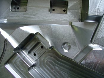
The LENS system integrates well with conventional processes to create unique hybrid manufacturing solutions. For instance, LENS can be used to enhance an existing component by adding layers of wear-resistant material or other surface treatments. LENS can also produce value-added features on existing parts, such as adding a boss, mounting lug, or flange to a large cast component.
Advanced Product Development and Functional Prototyping
A LENS system serves as a powerful product development tool that facilitates basic materials research, design feasibility studies and functional prototyping. LENS offers unique flexibility in the geometries and material range it supports, enabling the use of innovative design concepts such as hollow and internal structures, and functional material gradients that incorporate mechanical property transitions within a single part.

Once a geometry and material or material combination has been identified, LENS can rapidly produce a 3-dimensional prototype with excellent mechanical properties that not only give the designer a view of form and fit, but also enable full functional and structural analysis. The tool-less process is driven directly from CAD data, so a prototype of a new design or a design iteration can be produced in a matter of hours, providing significant time compression advantages.
Tuesday, November 15, 2005
LENS Aerospace & Defense
Component Repair
Optomec’s LENS systems provide a production ready repair platform that delivers economic and functional benefits in terms of: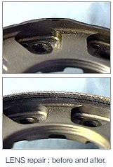
- Lower per-part repair costs
- Ability to repair heat sensitive components
- Reduced inventory requirements
- Longer service life
- Quick turnaround for rapid return to service
Key to its benefits, LENS is a highly targeted metal deposition technology that produces a very fine weld bead, exposing the component to far less heat than conventional methods. The resulting “heat affected zone” with LENS is smaller and more controlled so that the repair process does not damage the underlying part. And, since a LENS deposit is much finer and more precise than welding techniques, far less finishing work is required. Finally, with exceptional material and interface characteristics that are often superior to those of the native material, a LENS repair can potentially reduce future maintenance requirements.
Component Fabrication
High performance components are often made from specialty materials like titanium that are time consuming and expensive to produce using subtractive methods.
 In extreme cases, the Aerospace industry quotes “buy-to-fly” ratios for machined parts that can be as high as 15:1, highlighting the inefficiency and waste that is inherent in traditional methods.
LENS is an ideal alternative for producing such components because additive manufacturing provides for lower processing costs, faster turnaround, and significantly reduced material waste. The superior material properties with LENS serve to extend component life, reducing life cycle costs. The process also improves design flexibility by allowing novel geometries, structures and material gradients.
In addition to its ability to produce a complete part, LENS integrates well with other processes to create unique hybrid manufacturing solutions by adding high-resolution features to large forged or cast components, or by adding layers of wear-resistant materials as a protective surface.
US Army – Anniston Army Depot, Anniston, Alabama
The US Military’s maintenance operations alone support more than 500 ships, 16,000 aircraft, 50,000 ground vehicles, and other military assets at a cost of greater than $40 billion annually. The military repair applications for LENS cover aircraft, as well as land and sea based systems. In one example, the US Army’s Anniston Army Depot (ANAD) has been using its LENS system to repair a number of Honeywell gas turbine engine components for the M1 Abrams Tank. The Tank-Automotive & Armament Command (TACOM) has approved the LENS process, and ANAD estimates annual savings of up to $5 million using LENS to repair just a handful of approved components. With the success of this first system installation, ANAD has recently ordered its second LENS machine.
The US Army has also selected LENS for its Mobile Parts Hospital, which will provide a real-time battlefield repair capability that reduces the need to deploy large spare parts inventories and helps minimize down time of mission critical assets. The US Navy is implementing its first LENS system at the Naval Undersea Warfare Center (NUWC).
Sunday, November 13, 2005
Optomec LENS Technology
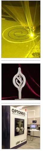 Optomec’s LENS - Laser Engineered Net Shaping solutions have evolved from technology that was pioneered at the U.S. Department of Energy’s Sandia National Laboratories under the direction of Dave Keicher who now serves as Optomec's CTO and Vice President of R&D.
LENS utilizes a high-power laser (500W to 4kW) to fuse powdered metals into fully dense 3-dimensional structures. The LENS system uses the geometric information contained in a Computer-Aided Design (CAD) solid model to automatically drive the LENS process as it builds up a component layer by layer. Additional software and closed-loop process controls ensure the geometric and mechanical integrity of the completed part.
With an Optomec LENS system, the process is housed in a hermetic chamber which is purged with argon so that the oxygen and moisture levels stay below 10 parts per million. This helps to keep the part clean and prevents contamination from oxygen or nitrogen. The metal powder feedstock is delivered to the deposition head by Optomec’s proprietary powder-feed system, which is able to precisely regulate mass flow. Once a single layer has been deposited, the deposition head moves on to the next layer. By building up the successive layers, the whole part is constructed. When complete, the component is removed and can be heat-treated, Hot-Isostatic-Pressed, machined, or finished in any customary manner.
Optomec holds numerous patents and has many patents pending on its proprietary LENS process and equipment.
Development History
The process underlying LENS is a mature technology kernel that has been under development for more than twenty years. Since 1997, Optomec has focused on making substantial investments in proprietary process, system and control enhancements in order to provide a robust solution that can meet the demanding requirements of industry. Likewise, Optomec has worked extensively with the US Department of Defense (DoD) and major aerospace, defense and medical device OEMs to ensure that commercial LENS systems address the production needs of our users.
Metallurgy Briefing
The LENS system can process a wide variety of metals including titanium, nickel-based super alloys, stainless steels, tool steels, etc. – all of which are commercially available in the requisite powder form. The results from LENS consistently demonstrate better metallurgical and mechanical properties than other processes due to an improved microstructure with significantly reduced grain sizes. For example, LENS-deposited 316SS typically has a cellular spacing of just a few microns, which leads to yield strengths approaching twice that of conventionally processed 316SS.
Friday, November 11, 2005
3D scanning made easy
One of Datron's latest products is set to make the copying of 3D objects cheaper and easier than ever before. The Copymate, by Israeli company Graphitech, is a scanner that simply plugs into any machine. The resulting computerised model can be edited before being machined into a finished item.Graphitech's objectives in developing the Copymate were ease of use and affordability. Installation is simple, and the user is guided by a wizard through the process of scanning, creating a machine tool path and sending the job to the milling machine. A by-product of this user-friendly approach is low operating costs to match its competitive price.The scanning itself is extremely rapid. An 8"x9"x3" object, for instance, can be scanned in 27 minutes, to an accuracy of 0.008 inches. Surface generation takes just 53 seconds, while the toolpath can be generated in four and a half minutes.If manipulation of the image before milling is required, the Copymate is complemented by Graphitech's Cimagrafi software. This art-based CadCam system is highly regarded in the industry, as it is intuitive, easy to use and built in a modular fashion, so it can be tuned to an individual customer's exact requirements. It has been a significant force in the market for the last five years. The release of Version 7, the next development, is hotly anticipated during this year.
Thursday, November 10, 2005
Goelan-innovative Cam software
Thanks to a new innovative, rapid and efficient method (based on the group's 30-year experience), the pure CAM software GOelan allows any company using digitally controlled machine tools to program them for unprecedented productivity.
GOelan is interoperable with the main CAD software packages (including TopSolid, but also numerous other CAD systems) and enables fast, simple and powerful programming for the manufacture of parts that are perfectly defined by a design or a sequence of NC commands.
Key features of GOelan
- Revolutionary, entirely redesigned interface
- Rapid familiarization - intuitive and comfortable to use
- Time savings times three
- Permanent management of modifications and errors
- Training made easy by 6 training wizards that can be called at any time
- Automatic re-calculation of blocks whenever a tool or machine is changed
- Selection of the tools definition order, schedules and areas to be machined
- Permanent control of the raw part or of the distance between 2 segments with a single tool
- Multiple viewing options that are easily identifiable and close to hand
- Wealth of industry-specific functions closely associated with your methods
- Integrated 2D and 3D programming
Other group products integrating CAD, CAM, and CAPM
In the manufacturing market, the strength of CAD/CAM suppliers lies in their ability to simultaneously provide design technologies and manufacturing technologies and to link them in a simple and yet coherent process. This must be supplemented by Engineering Data Management and computer-aided production management (EDM and CAPM). The strength of Missler Software is that, historically, it has thorough expertise in the twin fields of CAD and CAM. This competence is reinforced by a knowledge of CAPM systems for small and medium-sized enterprises, as used by more than 400 companies in France.
This gives rise to two perfectly compatible product lines, headed by Engineering Data Management and computer-aided production management:
TopSolid: This integrated mechanical CAD/CAM solution enables design and manufacturing data to be linked in a given environment for very diverse fields of mechanical engineering: machines, plastic parts, tooling, sheet metal work, general mechanical design, etc. TopSolid is designed for all manufacturers and subcontractors that need to do major design work related to manufacturing, and to simulate and control part production very precisely.
TopSolid/PDM and TopManufacturing: these solutions enable organization and management of all technical data and workflows implemented during the manufacturing and design processes.
Thursday, November 03, 2005
"CncPlayer", what is that actually?
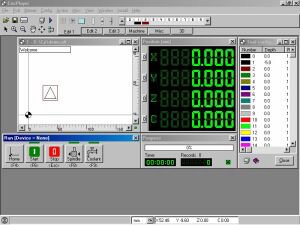
The CncPlayer is a software that plays your cnc files, hence CncPlayer or CP for short and controls your stepper motor driven cnc machine accordingly.
Even the CncPlayer is under construction, certain functions like cutter radius compensation, tool path optimization, DXF to HPGL (*.plt) conversion, milling simulation and more are already in an useful shape.
Tuesday, October 04, 2005
DeskCNC Software
DeskCNC is a Windows based CAM/CNC solution for creating toolpaths, copying existing models, and running CNC machines. DeskCNC can create toolpaths from DXF, STL, Gerber, Excellon, and Image file formats as well as Digitize existing part geometry (requires optional Probe or Laser Scanner). DeskCNC can smoothly run any CNC machine from within Windows. It includes a full G-code interpreter/editor and runs in any version of Windows 95/98/Me/Nt/2000/XP.The CNC Teknix DeskCNC Controller handles all linear and circular interpolation and times the output pulses with a resolution of 800 nanoseconds directly from Windows. It accepts a 24 bit (+- 8 million steps) absolute position and determines the ramp up, slew, and ramp down velocities based on a linear acceleration ramp profile. Continuous Motion Contouring is available for smooth cutting. It outputs standard +5v logic high and 0v logic low step/direction/output signals. The controller can be commanded to turn on four auxiliary relays (not included) if desired. It accepts Home switches, a limit switch, a Digitizing Probe, and an Emergency Stop switch. It is capable of providing a step pulse rate between 40 - 40,000 Steps per Second.
Monday, October 03, 2005
PowerINSPECT-Complex 3D Part Inspection
Inspection equipment and processes are both undergoing rapid changes as companies move from using 2D drawings to CAD models as the preferred method for product definition. This change, coupled with the rising demand for companies to prove the quality of their products, has lead to a growing demand for inspection methods that can be used throughout the prototyping, manufacturing and assembly chain. With these techniques, any problems can be highlighted earlier in the development process and so be corrected more quickly and at lower cost.
PowerINSPECT from Delcam leads the way in today's market by delivering a complete CAD based Inspection Solution. PowerINSPECT surpasses traditional 2 dimensional inspection methods by offering you the capability to inspect against all your CAD data with any type of measurement device.
PowerINSPECT can be used with all types of inspection hardware including manual and CNC CMMs, portable arms, optical measuring devices and CNC machine tools.
It provides quality with ease of use. having a simple user interface which is intuitive and easy to use. The learning curve is short allowing the operator to get the most from the measuring device in the shortest possible time.
PowerINSPECT's onscreen feedback and detailed graphical displays give immediate feedback for each measured point. Inspection reports can be generated automatically in a customised format to include pictorial, tabulated and statistical data, meeting the demands of design requirements and agreed International Standards.
Benefits include
- Comparison against all mainstream CAD formats
- Rapid alignment even for complex freeform shapes
- Inspection of user-defined sections
- The ability to inspect along the edge of a part
- Full Geometric Inspection capabilities
- Automatic creation of inspection features from CAD nominals
- A step by step Geometric Dimensioning & Tolerancing (GD&T) Wizard
- Point, wireframe and surface export for measured entities
- CAD manipulation - including surface offsetting (e.g. reverse side for sheet metal, spark gap for electrodes)
- Fully-customisable reporting in easy-to-understand formats
Sunday, October 02, 2005
Machining From STL Files-Part 2
Limitations
There is a downside to working with STL files. Perhaps the most obvious is that a faceted model is an approximation of the original surface geometry, which calls its accuracy into question. Practically speaking, however, this issue is relatively minor from the machinist's standpoint. Why? Sooner or later the model will become faceted anyway because all contouring moves in a 3D part program will be composed of linear movements in all but a very few exceptions.
One could argue that there is a doubling effect of laying tool path on an approximated model -- an approximation of an approximation so to speak. But one should also take into account that the facets of a tessellated model can be quite small. It's common practice to set faceting tolerances in the range of 0.001 mm (about 0.00004 inch) for machining purposes, says Mr. Howes. Moreover, the tool path processor can apply some relatively simple logic to more closely adhere to the base geometry. For example, on a convex form, the center of a linear path across a facet will obviously come closer to the base geometry, where on a concave form the edges of the facet will come closer, and the tool path processor can take these factors into account.
A larger issue for most shops will be the size of an STL file. For one thing, it takes a lot of triangles to accurately approximate a 3D form of any complexity. The file also contains a great deal of redundant information because the vertex coordinates of every triangle are stated individually. Since any given vertex will be shared with two or more adjacent triangles, each point will be stated two, three or more times. Also, the surface normal of each triangle is explicitly defined as a vector, which helps improve processing speed for rapid prototyping but mostly just adds unnecessary data for three-axis machining applications.
This large volume of data creates the temptation to attempt to reduce file size by loosening the faceting tolerance; but that's a bad idea if the facets become large enough to be seen in the actual machined surface. The faceting tolerance must be chosen in anticipation of the tightest machining tolerance to be used, says Mr. Howes, even though this means that the initial roughing calculations will be slower than is strictly necessary.
So, STL users will have to get used to large files. There are ways to compress the data to make files somewhat more manageable, and the faster computational speeds do a lot to mitigate the downside aspects of their size. In fact, Delcam contends that tool path calculation performance is still faster overall. But anyone wanting to machine from STL files will need to commit more than a little extra memory to the task.
Another significant issue, particularly if you live on the CAM side of the fence, is that there is little opportunity to edit an STL file once it has been output. The CAM system therefor must rely on the originating CAD system to have produced a good STL representation and to a suitable tolerance. That all depends on the CAD system's ability to consistently output good, closed models and on the CAD operator's knowledge of what tolerances manufacturing will require as well as an inclination to make sure all the necessary geometry is created in the first placenone of which is a given.
There are ways to correct moderately defective STL files. Delcam, for instance, has a feature called TriFIX that can sort out the connectivity of the facets and fill in small gaps, remove duplicate nodes, correct overlapping triangles and so on. Moreover, intelligence can be built into the CAM processor that makes it more forgiving of imperfect models. For example, when Delcam's PowerMILL CAM system is creating tool path from an STL model, it will automatically pass over a hole in the geometry smaller than the diameter of the selected tool.
But no patch kit can compensate for a faceting tolerance too loosely set or for a badly flawed file that's missing fillets, radii, or other important geometry. Those cases will demand a return to the original surface or solid model.
And finally, there is some useful information that will be lost when surfaces are converted to a faceted model. Surface boundaries, for example, will be gone. In many cases, these boundaries can be recreated with CAM functionality, but not always. Some flow cuts that follow individual surfaces may be sacrificed as well. Functions such pencil milling (where a tool is automatically driven along sharp surface intersections) are still possible, however, by using algorithms that analyze the faceted model, looking for abrupt changes in the "surface" normals.
More Applications
These limitations are going to relegate the STL file to a niche role well into the foreseeable future. But that role is likely to grow larger with time. Besides Stereo-lithography, the STL format has already become the de facto standard for other rapid prototyping processes such as selective laser sintering, laminated object manufacturing, and fused deposition modeling. Simple, faceted solid models also have other obvious applications in casting and molding process simulation, stress and thermal analysis, and other engineering functions.
Machining applications are likely to become more prevalent as well. But whether shops choose to machine directly from faceted solid models or not, they had best be aware of the STL format, since they'll likely be seeing more of those files in the future.
Saturday, October 01, 2005


Machining From STL Files-Part 1
If you think the STL file format is just a convenient means for programming rapid prototyping machines, think again. Here's how STL can work for machinists too.
If you are familiar with Stereolithography or other rapid prototyping processes, then you probably know all about STL files. If you only deal with CNC machining, then maybe you don't. But if your shop does a lot of 3D machining, the STL format is at least something to be aware of, and at most a tool that can speed and simplify the process of transferring and machining complex geometric forms.
The term STL, for Stereo-lithography tessellation language, refers to the representation of 3D forms as boundary representation solid models constructed entirely of triangular facets. In terms of the structure, it's rather like a geodesic dome, but one capable of representing -- as a single entity -- just about any free-flowing form that you'd ever want to machine. And machine from these forms you can, thanks to new developments in CAM technology.
The true beauty of the STL file lies not in its complexity, however, but quite the opposite, in its simplicity. The most basic of planar entities, the triangle, is used to describe everything. Each such "patch" is defined with just three points and an orientation vector. While it does take a lot of these triangles to represent 3D geometry, it liberates the file translation process and generation of tool path from many of the mistakes, missing data and ambiguous data inherent in working from translated surfaces and solids.
To find out more about where the STL format fits for machinists, we spoke with John Howes at Delcam International (Birmingham, England) -- one of the first CAD/CAM developers to use STL files for machining applications -- who has kindly provided most of the information for this article.
Mr. Howes is quick to point out that a faceted solid model is no panacea. It's not an original modeling tool, for design or for manufacturing. And while it can help make 3D file transfers and tool path generation less problematic, it won't make them foolproof. Still, the STL file can offer some very significant benefits in the proper applications, particularly to shops already in the business of machining prototypes, molds and dies. So read on and decide for yourself if STL files might have a place in your 3D machining operations.
Doing One Thing Well
The original intent of the STL format was to provide a means to unambiguously represent a solid model so that it could readily be turned into a physical prototype on a Stereolithography machine. The first STL specification was published by 3D Systems, Inc. (Valencia, California) -- developer of the Stereolithography process -- in July, 1988, and revised the following year.
The Stereolithography process is in many ways the exact opposite of machining. Rather than subtracting material from a solid piece of stock, a physical model is built from the ground up in thin horizontal layers by using a laser scanner to harden a liquid photosensitive polymer in the shape of the piece. The 3D CAD model, then, serves simply as a boundary from which this succession of 2D slices -- that correspond to each layer of the physical model -- is taken. To create "tool path" for the process, the laser beam is directed to trace about the boundaries of each slice to define its edges, and then to raster back and forth within the boundaries to harden the inner core. Though obviously serving a different purpose, the path is quite similar to that of a milling pocketing routine. And so it's not such a stretch to see that an STL model could also be used for machining, though now all the work is performed on the outside of the model, and often in three dimensions at a time, rather than just two.
By definition, an STL model is a completely closed boundary representation constructed entirely of triangular facets, the sizes of which are determined by a tolerance applied to an original surface or solid model. The STL format states that the facets are each described by the X-Y-Z coordinates of their three vertices and a surface normal vector that indicates the orientation of the facet and which side of it faces out. The format also includes rules to ensure that the triangles are all properly connected at the nodes.
Why are triangles such a good way of describing 3D models? "Obvious though it may sound," says Mr. Howes, "it is because there is really only one way to represent a triangle. By definition, they always have exactly three sides and vertices, so they are always planar and they can always be made to tile an area without gaps and overlaps. Every commercial surface or solid modeling system can generate accurate faceted representations of its models (even if only for color shading), whereas there are many different surface formulations. Even if you pick a single general representation like NURBS, there are still many different ways to represent the same geometry. Also, since STL is a much more tightly defined standard [due to its narrowly defined purpose and the proprietary environment in which it was developed], there are no different `flavors' from different CAD systems."
We should make clear at this point that no one initially creates geometry with an STL-type faceted model. Rather, 3D geometry is created with conventional modeling tools -- surfaces and solids -- and then converted to the faceted approximation of the original. A user-input tolerance is applied by a triangle-fitting algorithm, much in the same way that a cordal deviation tolerance is used to create 3D tool path from some form of reference geometry.
How Triangles Help Machining
Where do STL files pay off for machinists? According to Mr. Howes, "The key advantage of using the STL file format is that it communicates only the data that the NC programmer needs -- the geometry of the part. There is none of the extra information in the file to indicate the structure of the original CAD file." That helps simplify the process of transferring workpiece geometry from one system to another and also saves work and errors since the STL file is by definition a closed, unambiguous solid.
On the CAM side, not having access to all of the original surface data can at times prove to be a limitation, but that's certainly not a given. Indeed, if the STL file is properly constructed, it should preclude the NC programmer's need to get at the surface data in the first place. "Although the structure of a CAD model may be useful for machining, this is not always the case," says Mr. Howes. "Most toolmakers are familiar with the requirement to remodel parts of a job because the model structure didn't fit with their manufacturing requirements and the capabilities of their CAM software. Typically, many small surfaces may need to be combined so they can be machined as one, or fillets may need to be added to prevent gouging at surface boundaries that don't meet exactly. None of these modeling operations should be necessary when creating tool path from an STL file because the algorithms only rely on the shape of the part, not on the arrangement of component surfaces."
Moreover, Delcam contends that the original structure of a CAD model can adversely affect the tool path in some cases, depending on how the CAM system utilizes the surface information. For example, some CAM systems will ignore a fillet between two surfaces unless they are properly trimmed, and that will result in a gouge. And there's always the case where the CAD operator doesn't quite get around to making sure all the fillets are there to begin with, or to making sure all surfaces are properly joined, the latter of which may result in the tool "dropping through" an inadvertent hole in the geometry.
Delcam also argues that the calculation of tool path from a faceted model can be much faster than when working directly with complex surfaces. Because the mathematical representation of the faceted model is quite simple, the algorithms for generating tool path can be relatively simple as well, and more readily optimized. Conversely, when working from complex surface representations, the tool path algorithms must be able to cope with a much broader set of contingencies embodied in the math. The simplicity of the faceted model also permits the CAM developer to run many more tests on the quality of its tool path processor before each release of the software is shipped.
Sunday, September 25, 2005
Serial port monitor cable
Half Duplex
The schematic below is used to make a half duplex RS232 monitoring cable.
This cable is used for monitoring 2 devices communicating in half duplex fashion, that is, one device would send data and the other device would receive data. Both devices cannot transmit at the same time with half duplex, if that happened the data would be unusable.
Full Duplex
The next cable is used for monitoring full duplex RS232 communication.
Related Posts
Pinout an Signals Serial cable connection RS232-Serial Port DNC Software Verify Code
Serial cable connections
PC Com Port - EIA-574 RS-232/V.24 pin out on a DB-9 pin used for asynchronous data
X.21 interface on a DB 15 connector

RS232D uses RJ45 type connectors (similar to telephone connectors)
This is a standard 9 to 25 pin cable layout for async data on a PC AT serial cable 
Some applications require more pins than a simple async. configurations.
Related Posts
Pinout an Signals RS232-Serial Port Serial port monitor cable DNC Software Verify Code


